
Hoffmanamps Boardmaker InstructionsPage - Board Page 0 - Board Page 1 - Board Page 2 - Board Page 3 - Board Page 4 - Board Page 5 - Board Page 6To follow along with these pages you should go here to the library page and print out the layout diagram for the 5F6A Bassman board. |
|
|
Now it is time to install all the parts on the circuit board. The parts are suspended from top of lug to top of lug. Do not wrap the parts around the lugs. It
makes it very difficult to change a part if you wrap them. Start at the left end of the circuit board. Look at the layout diagram to determine what parts are going to be installed next. Usually most boards start with a resistor spanning two lugs and a capacitor spanning the same two lugs. The capacitor is sharing the same two lugs as the resistor. If you see the notation on the layout diagram, 820/220, this means there is a 820 ohm resistor spanning two lugs with a 220uf capacitor spanning the same two lugs. The positive end of all polarized capacitors always points toward the tube socket. Bias capacitors are the only exception. A bias circuit capacitor smoothes out negative voltage and the positive end faces the opposite direction. |
|
The parts are attached to the lugs by spanning two lugs and the neatest way to make that span is with the lead bender tools. The lead bender tools can be marked
with a sharpie pen for the most popular lengths that you are spanning. Most all of the lug spans are either 20mm, 30mm or 40mm. There are a few parts like the power resistors and
the parts that span a odd sized horizontal gap that are easier to just eyeball and bend by hand. Once you find the groove on your lead bender tool that seems to be best for each of these distances, you can mark that groove with a sharpie pen. It is way faster and easier if you have your most popular spans all marked on your lead bender tools. There is a bunch of information on this page on how to use the lead bender tools. I always face the resistors and capacitors the same direction on my boards. The resistors can face any direction, it just looks nicer having all the colors lined up the same direction. In other words the gold tolerance band on the 1/2 watt carbon resistors faces toward the pots. I always face the brown Xicon coupling capacitors with the writing facing towards the left end of the board. Non polarized coupling capacitors don't really have a positive and negative end but one leg of the cap is tied to the outside of the cap. I always thought it was a good idea to have this leg facing the more negative connection. This may help act like a shield and prevent cross talk or coupling between other capacitors that may be very close together. Continue mounting the parts to your circuit board. I mount all the parts before I do any soldering. It is easy to think that a lug is finished and can be soldered. Then you look at the diagram and see that there is another part that has to be inserted into that lug. If you have already soldered the lug it will be messy and difficult to add the part that you forgot. So my recommendation is to be careful and not knock any of the parts off the board while you are mounting them, then solder all the parts at one time when you are done. I have a small jewelers screwdriver that I sharpened to a point on my bench sander. I use this tool to push down inside a lug hole to make it larger. If you look at the bias pot photo below you will see 3 parts stuck into the same hole. The bias pot leg is not round in shape so it is hard to shove 3 parts in without reshaping the lug hole. Once you have 1 or 2 parts in a lug hole you can shove your pointy tool down inside and the lug hole can be reshaped to accept another part. The power resistors have larger wire legs than a 1/2 watt resistor and I usually have to reshape the lug holes where a power resistor is attached. |
 |
 |
 |
| The layout diagram | The parts mounted | Parallel parts |
|
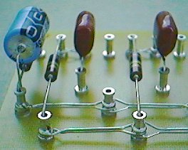
Here you can see the parts mounted but not soldered to a 5F6A circuit board. You can also see the end view of the first two parts at the left end
of the board in parallel. The layout diagram above is the same as the small circuit board section with parts mounted. Now you can see how a layout diagram relates to the actual parts
on the circuit board. The two empty lugs on the layout diagram and on the circuit board are a feature that I included in some circuit boards. Some circuits share a common cathode resistor and capacitor. Look at the layout diagram and notice the jumper wire that goes from pin 8 to pin 3 on the back of the tube socket. Then notice that the wire goes to the 820 ohm resistor with the 220uf capacitor in parallel. Both cathodes of the pre amp tube, pin 3 and pin 8 are sharing a common cathode resistor and cap. I left space on the board to be able to give each cathode it's own resistor and capacitor combo. You can dial in each pre amp input differently if you want to with this method. If you are going to separate the cathodes, the jumper wire from pin 3 to pin 8 is removed and a new wire is added from pin 8 to the top empty lug. Marshall pre amps have two different sets of resistors and caps for two different sounding pre amp inputs. |
||
 |
 |
||
|
|
|
||
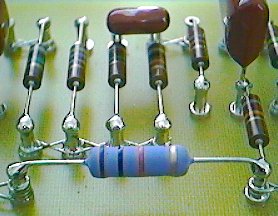
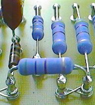
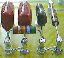
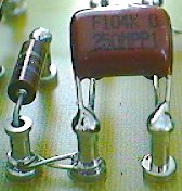
| There are usually a few parts on most circuit board layout diagrams that span lugs horizontally. The large resistors in the photo's above are the 10K and 4.7K power supply resistors on the 5F6A board. The power resistors appear horizontally along the front edge of the 5F6A layout diagram. The small resistor in the photo below is the 56K resistor that appears along the top edge of the 5F6A layout diagram. The capacitor photo below is the .1/250v cap that spans the gap between the 1meg and 10k resistor along the front edge of the 5F6A layout diagram. It is easy to forget to install the two parts below, double check yourself. | |||
 |
 |
|
 |
 |
 |
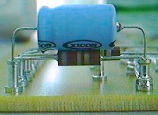
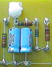
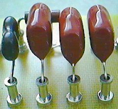
Here you can see the complete 5F6A bias circuit at the right end of the 5F6A board. Notice the 15K resistor spans two lugs horizontally. The 2 big blue bias
capacitors face the opposite direction as the other big 220uf cap at the left end of the board. The positive ends of the bias caps are going to a ground buss because the other end
of the cap has the negative bias voltage on it. The bias voltage is more negative than ground so the negative end of the bias cap goes towards the negative bias voltage. The bias diode is next to the big blue caps. Notice the silver stripe on the diode faces the ground buss. The diode is rectifying negative voltage so the diode stripe must face this direction. If you install it backwards you will have positive voltage in your bias circuit. Your power tubes then will go into a runaway current situation. Don't forget to solder the two front legs of the bias pot. |
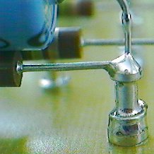 |
Here you can see how solder is applied to each lug that needs to be soldered. Notice the nice small dome of solder. It is not necessary to put globs of solder
on each lug. Do not apply too much heat to components when you are soldering them. Bring your soldering tip and solder together at the same time on the lug and pull away as soon as you see the desired dome of solder. Make sure the solder has actually flowed and stuck to the lug and stuck to the parts in the lug hole. If you come in and leave too quickly before the solder flows properly, you may end up with a bad solder joint that is not making proper electrical contact. |
 |
I actually do not solder every lug. Some of the parts on the board have wires that lead over to the pots on the front panel of the amp. It is easier
to solder the pots and pot wires last when installing a board in an amp. It gets very tight and hard to work inside the amp at this stage of a board install. I found that if
you push your pot wires down inside the lug instead of trying to wrap the pot wires around the lug it is easier to install the pot wires. This is a personal preference and you can
do it any way you like. On the layout diagram you will see small numbers on the back of the pot connections and you will see those same numbers next to a part on the board. This indicates a wire connection from a pot to the circuit board. The small number connections are the ones that I do not put a solder dome on. One end of the part is soldered and the number end is not. The example here is the tone stack capacitors that lead to the tone pots. |
|
|
Enter My Tube Amp Parts Store Here
Mobile users Enter My Tube Amp Parts Store Here
The Tube amp Library of information
Click the link above for Tube amp info, Schematics, Board building information, Projects, Mods, Transformer diagrams, Photo's, Sound clips.
There are hundreds of pages of Tube amp information on my library page.
Please visit my Tube Amplifier Forum
Here's the place you can go to ask tube amplifier questions.
You will find a large community of friendly amp builders at the link above.
Check the huge library of Schematics here
Design your own custom Turret Board or Eyelet board
DIY Layout Creator file analyzer program
DIY Layout Creator file library
How to email me
|
MEMBER OF PROJECT HONEY POT Spam Harvester Protection Network provided by Unspam |