


Hoffmanamps Boardmaker InstructionsPage - Board Page 0 - Board Page 1 - Board Page 2 - Board Page 3 - Board Page 4 - Board Page 5 - Board Page 6To follow along with these pages you should go here to the library page and print out the layout diagram for the 5F6A Bassman board. |
| - |
|
|
|
Here's a couple Youtube videos of me lacing the lugs and soldering them |
 |
Now we are going to lace the circuit board. Lacing is the process where lugs are joined together in a buss. A buss may be just two lugs or a buss can be several lugs joined together.
Lacing lugs together is how lugs are joined together electrically. For example on most of my boards there are several lugs that all must be grounded. Instead of running a separate
wire from each lug to ground, the lugs are all laced together and then one large wire is connected to ground which lets all of the lugs go to ground. |
 |
 |
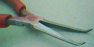
The circuit board needs to be screwed down to a bench top or held solid while you lace the circuit board. I use two screws and screw the board to
my bench through two of the mounting holes. First take a fine pair of bent needle nose pliers and make a 3/4 loop on the end of the buss wire. These pliers are Snap on model E704ACG and work the best of any tool I have tried. |
 |
|
|
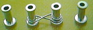
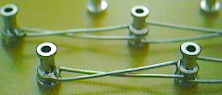
Hook the 3/4 loop you made above around a lug at the end of a buss and then hold the loop tight against the lug with the pliers. Take the buss wire
and pull it back and forth between the lugs that you want to join together. If you have a large gap to span make a 360 degree loop around a lug before you continue on to the next
lug. If you are just joining two lugs that are next to each other, you do not have to make a double 360 degree loop. Continue to lace all lugs together by looking at the layout diagram
to see which lugs get joined. The top photo shows how the buss spans large gaps. Notice the double loops around the lugs. The bottom photo shows two lugs joined side by side. |
 |
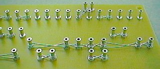 |
Push all buss wire loops down so that they as close to the board surface as possible. I use a small dental tool I found at a flea market. It has a small 90 degree
hook at the end of the dental tool. Here you can see the right end of a board that has been laced. Notice there are lugs everywhere that have been joined together on a buss. Some busses are just two lugs and some busses have as many as 7 lugs joined together.
|
 |
Now it's time to solder all the lugs that have been laced. Put the tip of your soldering iron against the lug and touch the solder to the lug lacing at the same
time. The solder will start to melt and you must make the solder flow around the lug so that the buss wire has solder all the way around the lug. You do not need a ton of solder.
Do not flood the lug with solder. Soldering is an art and takes time to get good at it. Use some sort of small fan to suck the solder fumes away from you. If any buss wire pops up from the heat you can reheat the lug and hold the buss wire down with some sort of tool. |
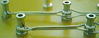 |
This step is not necessary, but I think it makes the boards look much better. On the longer buss wire spans I will take two pairs of pliers and pinch together
the buss wire so that the two wires are grouped together side by side. I only do this on lugs that are 3 or more lugs apart from each other. See the before photo above. |
|
When you solder the lugs, small spots of resin will spray onto the board surface, this is normal. The resin is inside the solder and helps the solder flow properly
when the solder is melting. The resin is soft and gooey at first but will firm up if you wait a few minutes. The cooler the room temperature the quicker the resin will firm up. After the resin hardens, I take a small flat object and scrape the board clean of all these resin spots. If you scrape the resin spots before they firm up, the resin will just spread around the board and make a mess that is hard to clean up without some sort of very strong chemical. I don't use any chemical to clean my boards. I don't want to breath the fumes from a strong chemical in my shop. |
| Now all the lugs with lacing should be soldered and you should have a clean board with no solder resin spots. |
Enter My Tube Amp Parts Store Here
Mobile users Enter My Tube Amp Parts Store Here
The Tube amp Library of information
Click the link above for Tube amp info, Schematics, Board building information, Projects, Mods, Transformer diagrams, Photo's, Sound clips.
There are hundreds of pages of Tube amp information on my library page.
Please visit my Tube Amplifier Forum
Here's the place you can go to ask tube amplifier questions.
You will find a large community of friendly amp builders at the link above.
Check the huge library of Schematics here
Design your own custom Turret Board or Eyelet board
DIY Layout Creator file analyzer program
DIY Layout Creator file library
How to email me
|
MEMBER OF PROJECT HONEY POT Spam Harvester Protection Network provided by Unspam |