
3D Printer Build using 20mm T-Slot extrusionsBack to my main CNC page |
|
|
This is my second 3D printer build It is a refinement of printer #1 build After using printer #1 for a while I have dialed in the design and so I set out to build printer #2 based on that design Printer #1 printed many of the custom pieces for printer #2 Note that I only print with PLA plastic because it is very easy to work with You can print at lower temperatures and PLA does not require a heated bed It is much less hassle than ABS plastic Here's printer #2 spec's The print bed is (X axis) 228mm x (Y axis) 236mm x (Z axis) 280mm The Frame is 20mm T-Slot extrusions from 8020inc on Ebay I made all the linear bearings on my CNC machine from UHMW Plastic. The UHMW is from Mcmaster-Carr There are no lead screws and no smooth rods, all movement is done via GT2 2mm belts and pulleys There are 4 x GT2 2mm drive belts and 8 x GT2 20 tooth pulleys 4 x Nema 17 Stepper motors 2 x Metal drive shafts move the Z axis up and down using 2mm GT2 belts and pulleys I use a 12volt 40watt cartridge heater for the extruder Probotix driver boards, breakout board and power supply Gnex lab dual temp control board for the hot end and heater bed Ball bearing filament spindle so the filament spool rotates with very little effort The G-Code is created using Slic3r I am running the G-code using Mach3 I use Mach3 because I am already familiar with it. I use it on my CNC machine. All the yellow, green and black flat material you see in the images below is G10 Garolite from McMaster-Carr I machined all the Garolite pieces on my CNC machine All the black plastic pieces you see in the images below were printed on Printer #1 Here's a YouTube video of the new printer |
|
| Click on the images to see a larger image | |
 |
 |
|
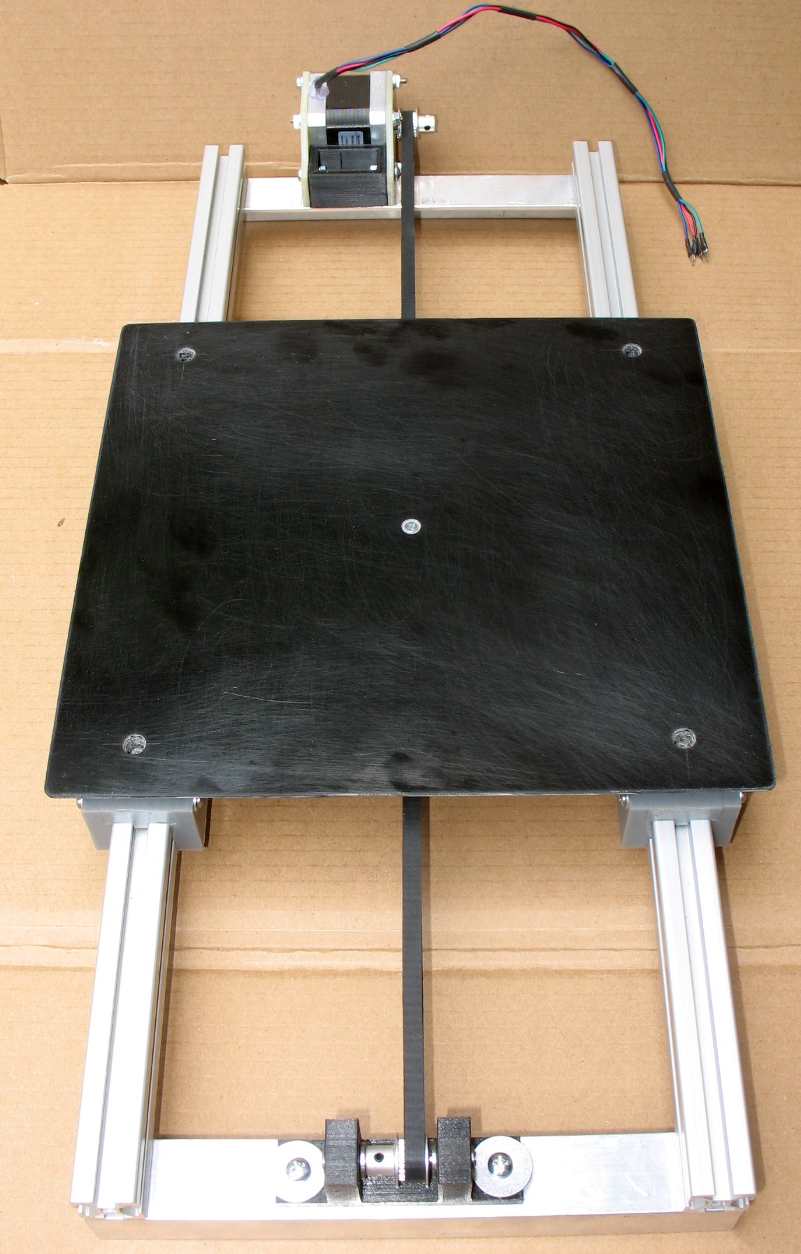
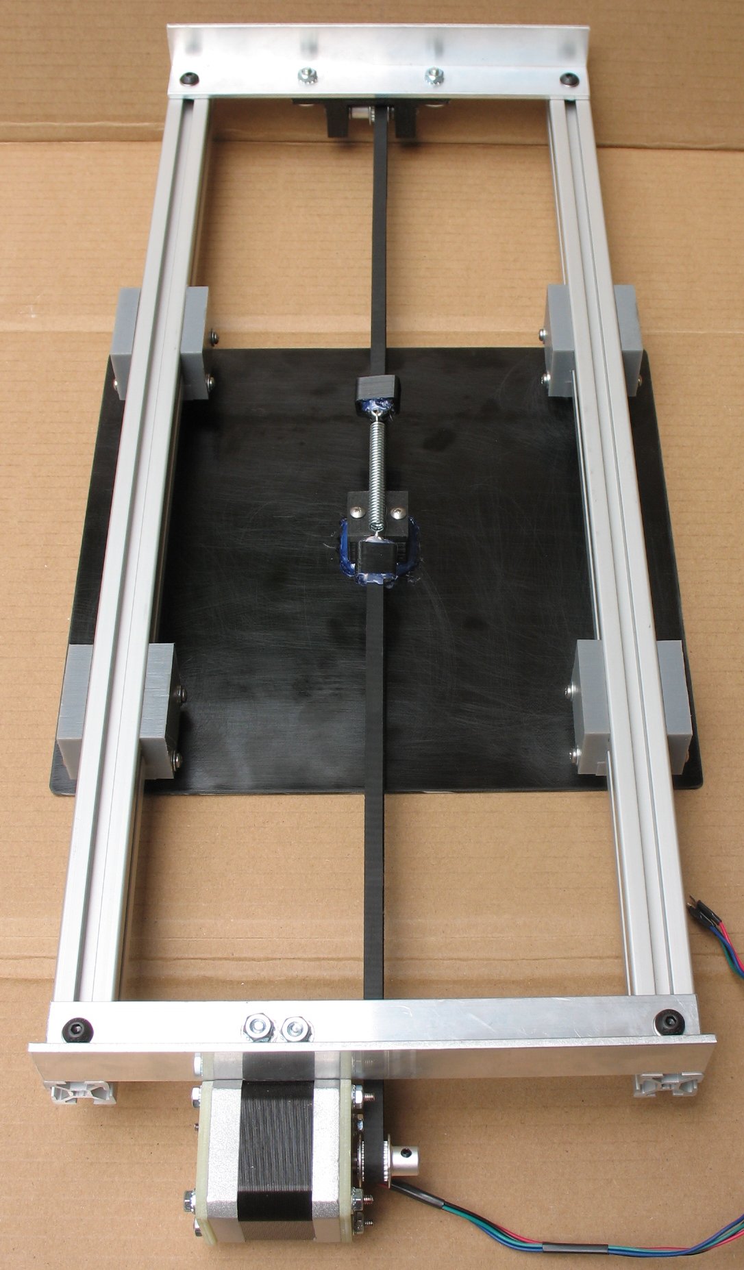
This is the Y axis bed. The black Garolite material sits on 4 round plastic pucks. Those pucks are glued to the Garolite sheet A screw goes through the Garolite and the puck and then screws the puck to the UHMW bearings. Once the machine was assembled, I slid shims under the pucks to get the bed within .001 inch level on all four corners A piece of glass is taped down to the top of the Garolite to get a perfectly flat printing surface. Blue painters tape is taped down to the glass surface PLA plastic sticks really nice to the blue painters tape The idler pulley assembly was printed on printer #1 There are two Oilite bearings pressed into the black plastic idler assembly 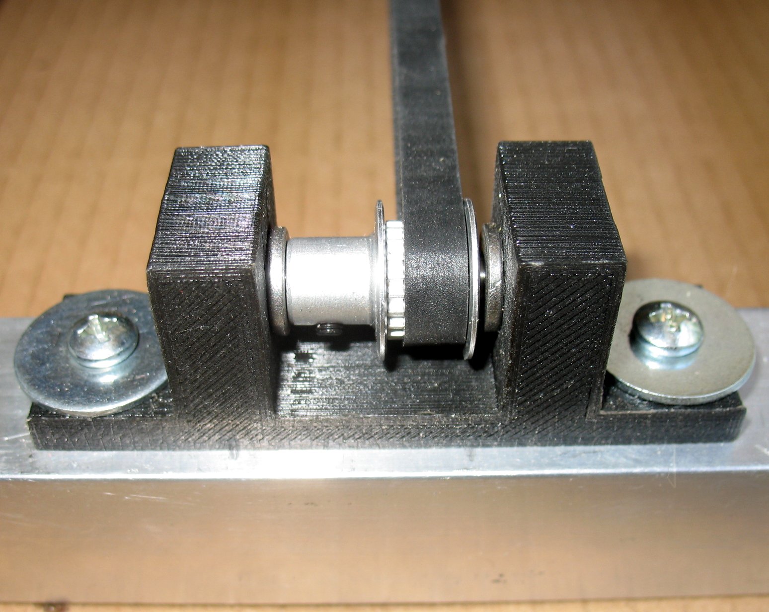 |
|
| - | |
| Click on the images to see a larger image | |
 |
 |
|
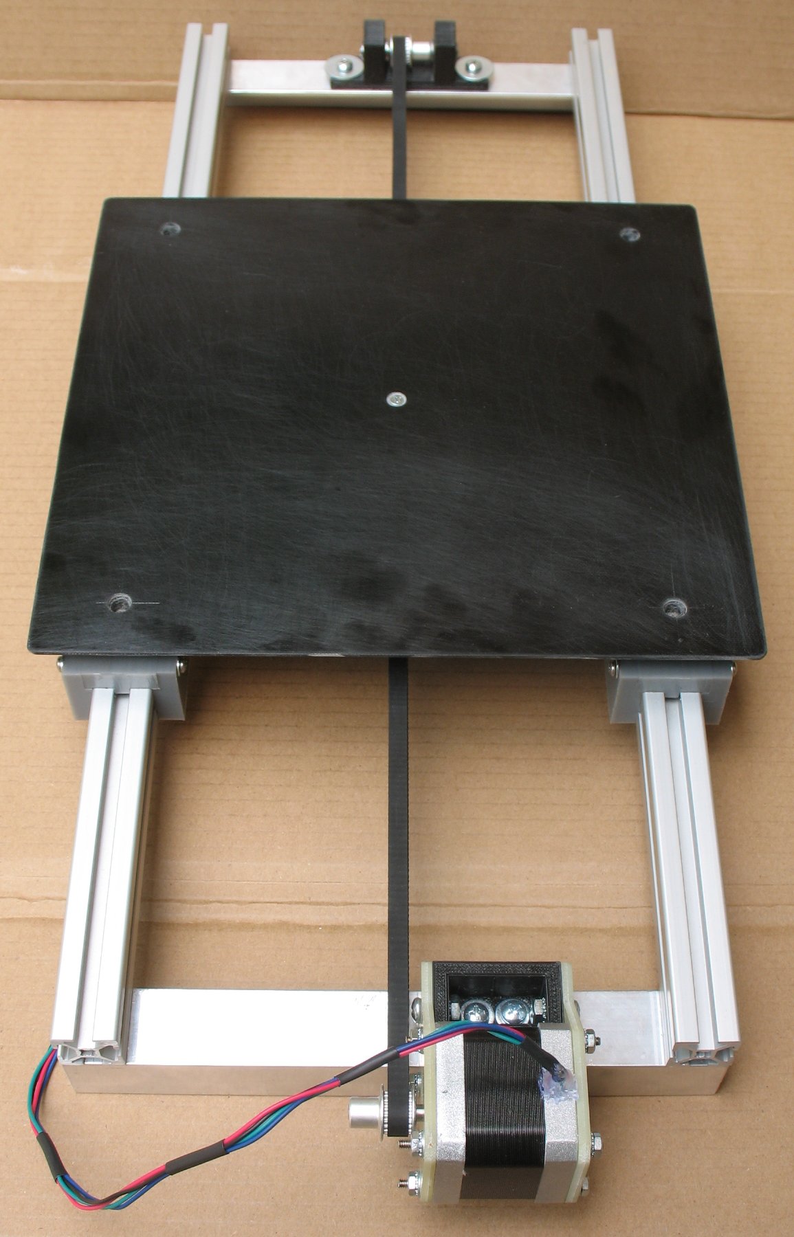
Here's a shot of the underside of the Y axis You can see the UHMW bearings and my belt tension device A spring pulls the two belt ends together and keep the belt tight The belt end clamps and the center belt clamp were printed on printer #1 I reinforce some of the parts connections with hot glue The UHMW bearings can be adjusted via shims and screws to take up slack and get the right friction level  |
|
| - | |
| Click on the images to see a larger image | |
 |
 |
|
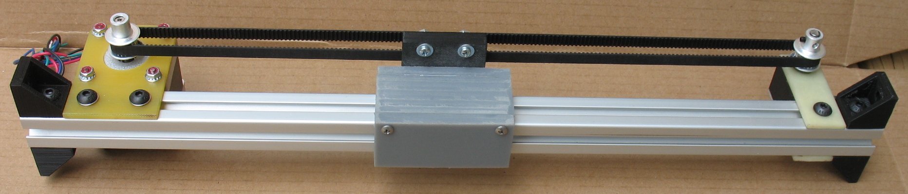
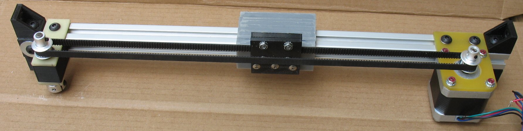
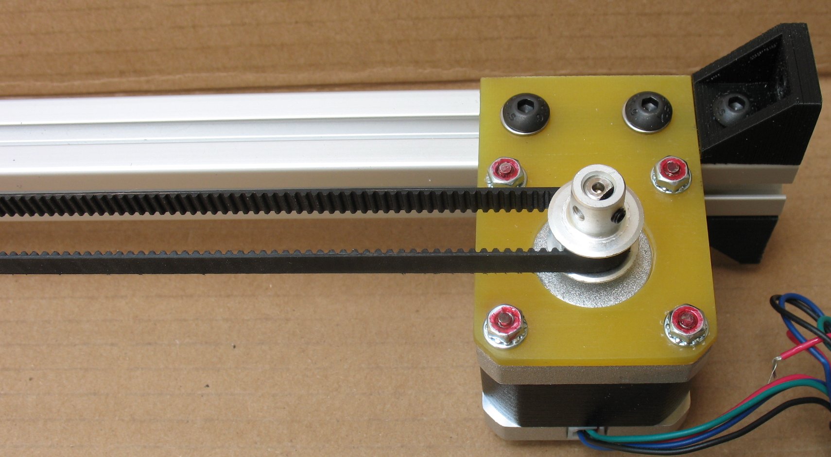
This is the X axis On this build I have the motor and idler pulley bolted firmly to the 20mm T-slot This makes the X axis very rigid. This new design turned out very well I put tension the belt by moving the idler pulley end and tightening down 3 screws The black plastic ends get bolted to the Z axis 20mm T-slot upright pieces |
|
| - | |
| Click on the images to see a larger image | |
 |
 |
|
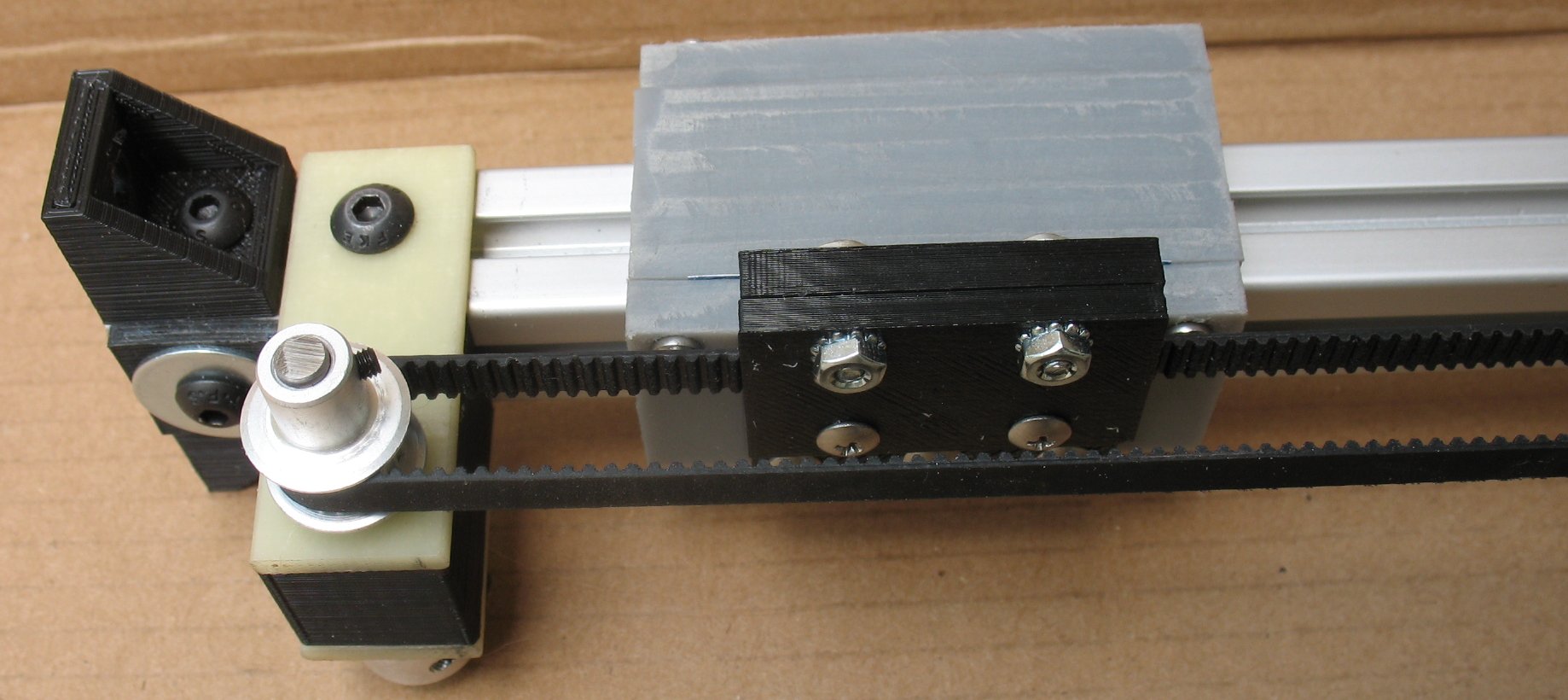
Close ups of both X axis ends You can see the belt clamp and how it is attached to the linear bearing The belt clamp, the idler pulley center section and the 90 degree brackets on the ends of the T-slot material were printed on printer #1 I use 5mm Allen head screws and T-slot nuts to connect the angle pieces to X axis T-slot piece I used 4/40 threaded rod to connect the angled pieces to the Z axis linear bearings The motor is attached to a 1/8 inch thick Garolite bracket That bracket is bolted to the 20mm T-slot using 5mm bolts and T-Slot nuts 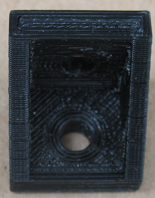 |
|
| - | |
| Click on the images to see a larger image | |
 |
 |
|
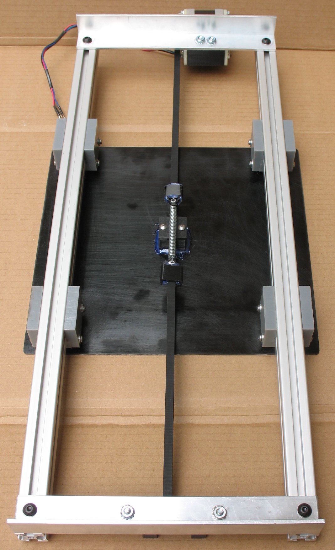
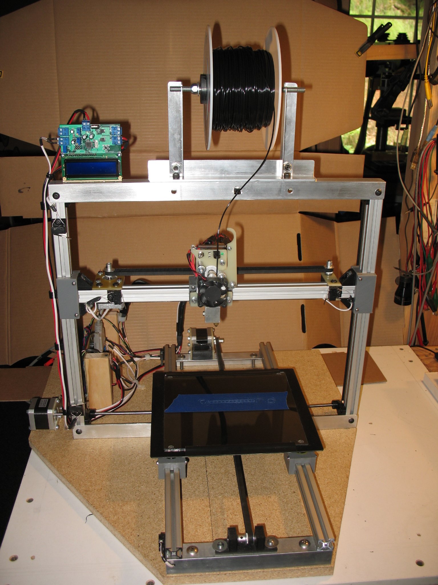
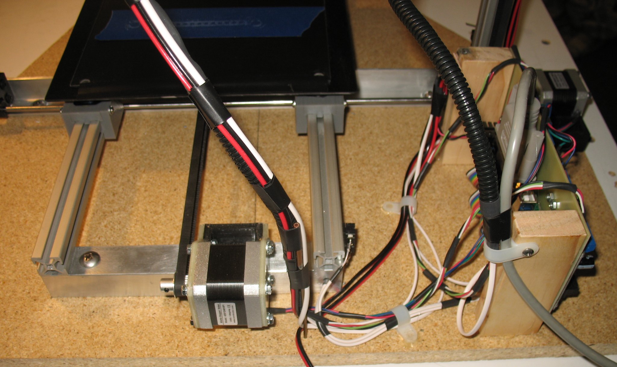
The assembled printer You can see the glass printing surface with some blue painters tape applied The black Garolite bed was leveled with .005" shims at all four corners and so the glass sits on a level surface When printing small parts, I only stick down a small piece of blue painters tape The tape is only good for a couple uses or until it rips so it's not a good idea to cover the entire glass piece with tape I only use enough tape to get the job done If I was printing a large area I would have to cover the glass for that area I am using 2 inch wide blue painters tape Right: You can see how the Y axis motor connects to a drive shaft The drive shaft has a 2mm GT2 pulley on each end Two GT2 belts go up to the second drive shaft at the top of the printer The 2nd drive shaft also has a GT2 pulley on each end The two drive shafts and four GT2 pulleys pull end end of the Z axis up and down evenly On a 3D printer the Z axis only creeps up .2mm with each layer that is printed The Z axis does not move up and down rapidly like on a CNC machine The Z axis only returns to Zero when you start a new print Z axis zero is when the print head nozzle is touching the blue painters tape |
|
| - | |
| Click on the images to see a larger image | |
 |
 |
|
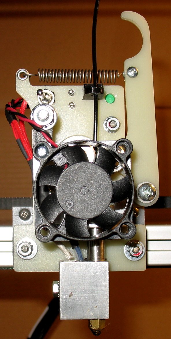
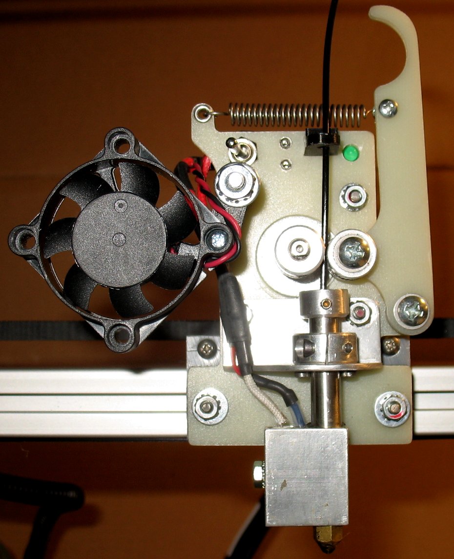
This is my latest print head design A big improvement over my first few designs This hot end design produces very clean prints The Nema 17 motor is bolted to a Garolite support All the other pieces shown are bolted to the Garolite support The Garolite support is bolted to the UHMW linear bearing There is a relief cut on each side that lets me get access to the two UHMW bearing screws There's allot going on in these pictures so here's how it all works Starting at the bottom of the extruder: The brass nozzle tip is a Makerbot style tip. I am using these nozzles because they work really well and they are only $5 each I can't make a nozzle tip for $5 so it's better to just buy them The nozzle has 6mm threads and it screws into the aluminum heater block The aluminum heater block has 3 holes drilled into the top Hole 1 is for the stainless steel hollow tube which is pressed into that hole using a small press I have in my shop Hole 2 is a small 1/8th inch hole that the thermistor tube slides down into to sense the hot end temperature Hole 3 is where the 40 watt heater cartridge goes There is a small set screw and nut on the left side that holds the 40 watt heater in place A stainless steel tube is used because stainless steel does not transfer heat very well compared to many other metals The stainless steel tube has a PFTE tube inside it The PFTE tube has a small 2.3mm hole drilled down through the center The 2.3mm hole guides the 1.75mm PLA filament down to the hot end The PFTE tube insulates the PLA filament so it does not melt on the way down to the hot end It is very important to keep the filament rigid because you cannot push it if the filament will become soft on the way down It's like pushing a piece of rope The PLA filament only melts when it reaches the brass nozzle The Stainless steel tube is clamped in place using an aluminum collar with a set screw The collar is screwed down to an aluminum angle piece At the top of the stainless tube is a small collar that keeps the PFTE tube from being pushed out of the stainless tube. The top collar has a small set screw to keep it from moving When the PLA plastic is forced down into the hot nozzle, there is allot of pressure trying to push the melted plastic back up If the PFTE sleeve is not kept in place it will just pop out of the top and the hot end will stop working The PFTE tube has a chamfered hole at the top to make filament loading easier The Nema 17 motor has an aluminum gear with teeth that grip the PLA filament There is an idler gear to the right of the motor gear and that gear also has teeth Both gears have a concave tooth shape that the PLA filament rides in The idler gear pushed hard against the filament forcing it into the motor gear The idler gear is on a pivoting arm that has a spring The pivoting arm has a finger indent at the top The spring is what pulls the idler gear into the motor gear Here's a shot looking down from the top 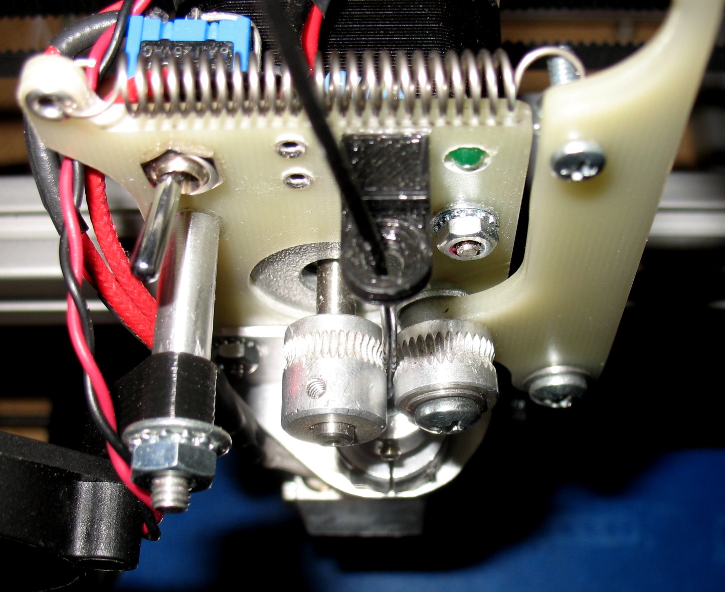 Above the gears, the filament goes through a plastic guide that was printed on printer #1 The 40mm fan keeps the upper stainless tube and aluminum parts cool and the fan can pivot out of the way if needed Upper Left: There is a switch to turn on the 40 watt heater cartridge Upper Right: There is a green led that is on when the heater is on The thermistor tells the temp control board what the temp is and the The temp control board controls the 40 watt heater The heater turns on and off when the printer is printing Update 01/05/2014. I upgraded the filament roller to a ball bearing roller that I got out of a disk drive. Here's a movie of that upgrade |
|
| - | |
| Click on the images to see a larger image | |
 |
 |
|
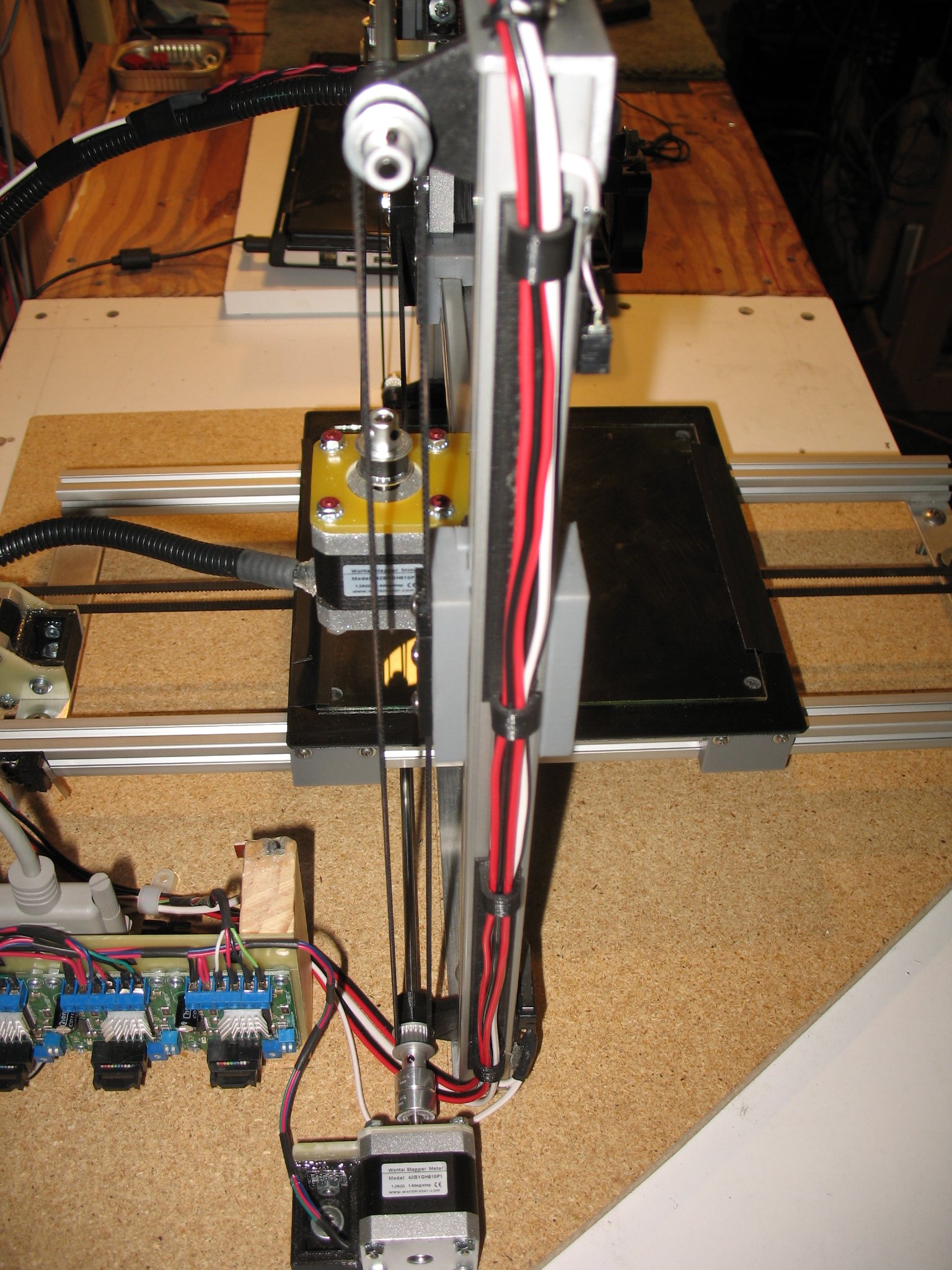
Left: Here's a back view of the printer You can see all the wires that go to the extruder There are 4 motor wires, two heater wires, two thermistor wires and two fan wires This wire assembly has to be very flexible to be able to go left and right, up and own the full range of the X and Z axis The X axis motor also has a separate wire bundle There are four motor wires and 2 limit switch wires This wire bundle only needs to go up and down with the Z axis Right: You can see the Y axis motor and bunch of wires |
|
| - | |
| Click on the images to see a larger image | |
 |
 |
|
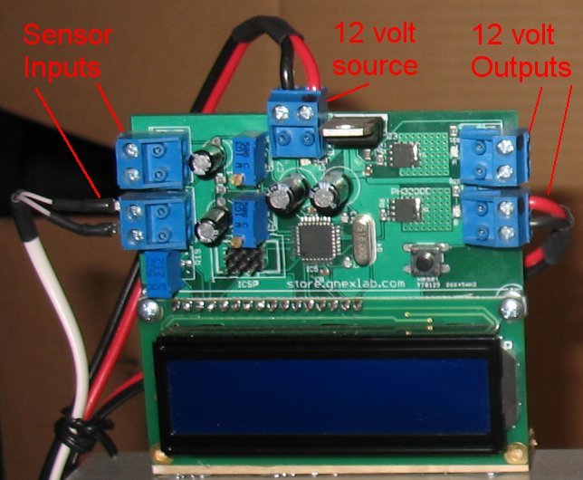
Left: The 4 Probotix stepper driver boards used to control all four motors Note that most of the Reprap printer builders use different drivers and control software I have a CNC machine that uses these same driver boards and I use Mach3 to run the Gcode and so I stuck with what I already know Right: You can see the Gnex temp control board and my filament spool holder The Gnex board can control two heat sources in case you also want to run a heated bed for ABS printing I am only using one of the sources to control my hot end heater There are two thermistor inputs and two 12volt outputs There are two multi turn pots so you can dial in the exact control temp you want the unit to control The board reads the thermistors and then turns the 12volt DC outputs on and off to what ever you have set the trim pots to. I print 1.75mm diameter PLA filament at 180 degrees Celsius Link to Gnex temp control board Links to my Probotix Electronics Probotix SideStep Stepper Motor Driver Probotix PBX-2 CNC Parallel Port Breakout Board |
|
| - | |
| Click on the images to see a larger image | |
 |
 |
|
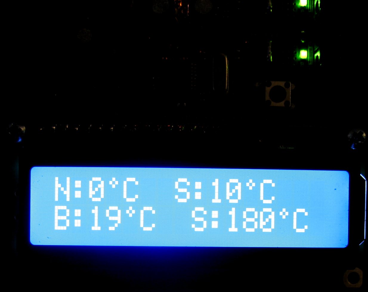
Left: The display on the Gnex control board. The top line in the display is one control, the bottom line is the other control. I am using the bottom controller for my hot end. The B:19C is the current temp of the hot end because I have it turned off and it is at room temperature The S:180C is the temp I set the pot to and is the temp I want the board to remain at while printing When I turn the heater on, the temp on the left will continue to rise until it is at 180C Then the board will continue to monitor the temperature It will then turn the heater on and off, trying to keep it at 180C Right: This image shows the two sensor inputs, two 12 volt outputs and the 12 volt source input The 12 volt source needs to be a very beefy 12 volt dc power supply I am using a 7 amp 12 volt power supply The 12 volt heater on my hot end pulls 3.5 amps when running I am not sure what the 4 motors are pulling when running, I have not measured that You can use a computer power supply. It has 12 volt dc outputs. The 4 wire plug used to power the disk drives has a 5 volt and 12volt source The yellow wire is +12volts Dc, the red wire is +5 volt dc The two black wires are common grounds Use the yellow wire and one of the blacks to get 12 volts DC Computer power supplies usually have the current ratings on them so you can see if it can deliver enough amps. If you are also running a heater bed, most likely you will need at least a 10+ amp 12 volt dc power supply |
|
| - | |
| Click on the images to see a larger image | |
 |
  |
|
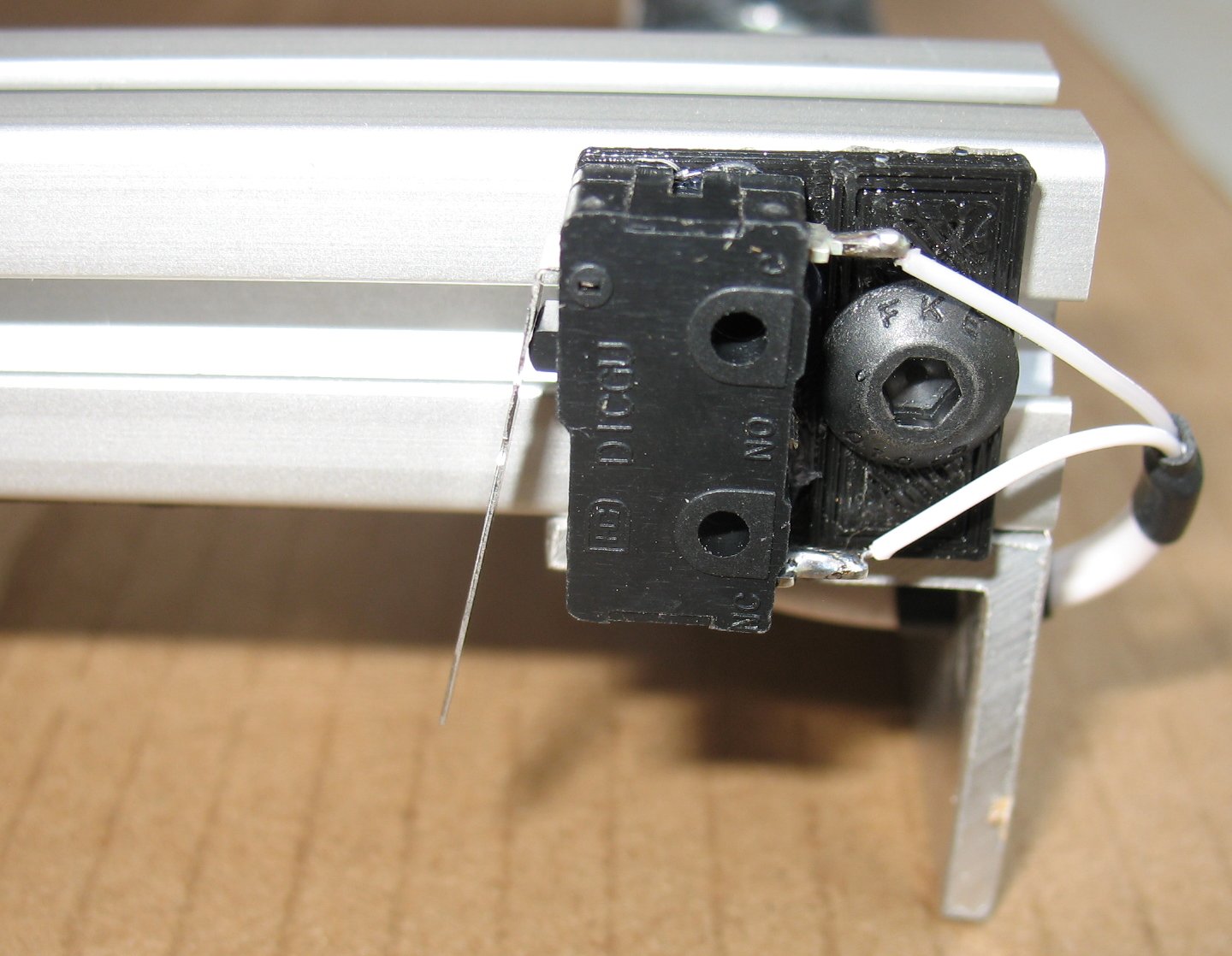
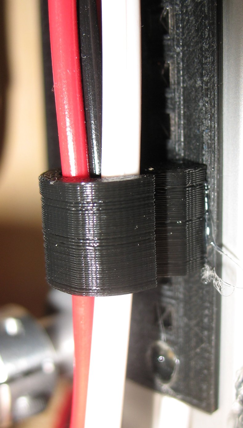
Left: A shot of one of the six limit switches The limit switches will stop the motor if a switch is triggered This keeps the motors from going beyond the limits of their maximum travel Each axis has a limit switch at both ends Right: Here's a shot of one of the nifty wire clamps I designed and printed for this printer I hot glued them in place to keep my wire bundles nice and neat |
|
| - | |
Enter My Tube Amp Parts Store Here
Mobile users Enter My Tube Amp Parts Store Here
The Tube amp Library of information
Click the link above for Tube amp info, Schematics, Board building information, Projects, Mods, Transformer diagrams, Photo's, Sound clips.
There are hundreds of pages of Tube amp information on my library page.
Please visit my Tube Amplifier Forum
Here's the place you can go to ask tube amplifier questions.
You will find a large community of friendly amp builders at the link above.
Check the huge library of Schematics here
Design your own custom Turret Board or Eyelet board
DIY Layout Creator file analyzer program
DIY Layout Creator file library
How to email me
|
MEMBER OF PROJECT HONEY POT Spam Harvester Protection Network provided by Unspam |