
3D Printer Build using 1 inch T-Slot extrusionsBack to my main CNC page |
|
|
This is my first 3D printer build Here's the printer spec's The print bed is 200mm x 200mm X and Y axis x 254mm for the Z axis The Frame is 1 inch T-Slot extrusions The Bearings are T-Slot linear bearings that use UHMW Plastic. There are no lead screws and no smooth rods There are 4 x GT2 drive belts and 8 x GT2 20 tooth pulleys 4 x Nema 17 Stepper motors 2 x Metal drive shafts with bronze oil lite bearings 40 watt cartridge heater for the extruder Probotix driver boards, breakout board and power supply Gnex lab dual temp control board for the hot end and heater bed Ball bearing filament spindle The G-Code is created using Slic3r I am running the G-code using Mach3 All the yellow-ish colored material you see in the images below is G10 Garolite I machined all the Garolite pieces on my CNC machine I have several videos on YouTube of this printer in action Here's one of them |
|
| Click on the images to see a larger image | |
 |
 |
|
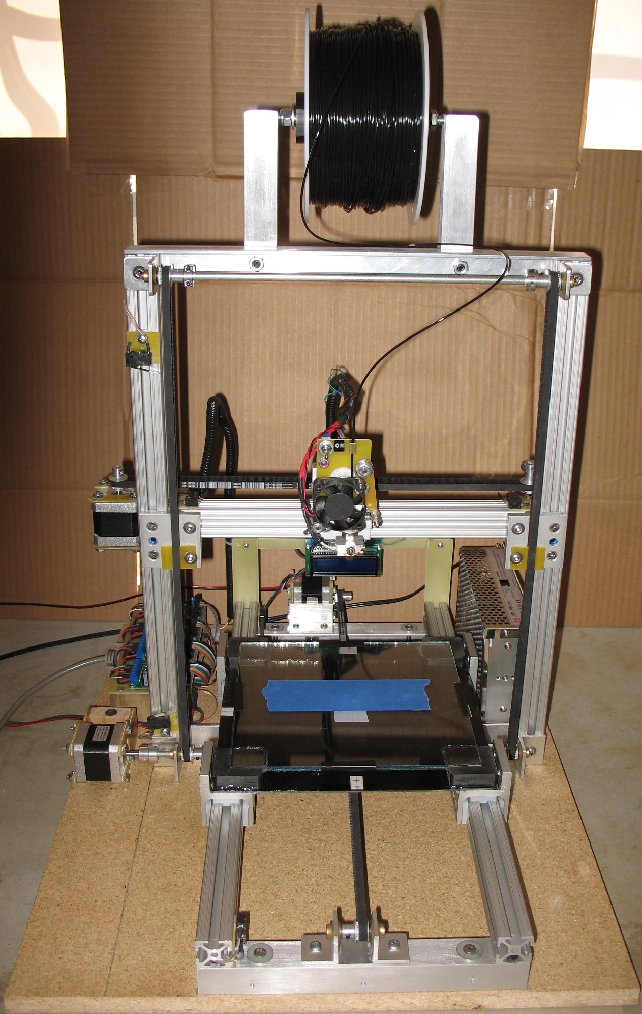
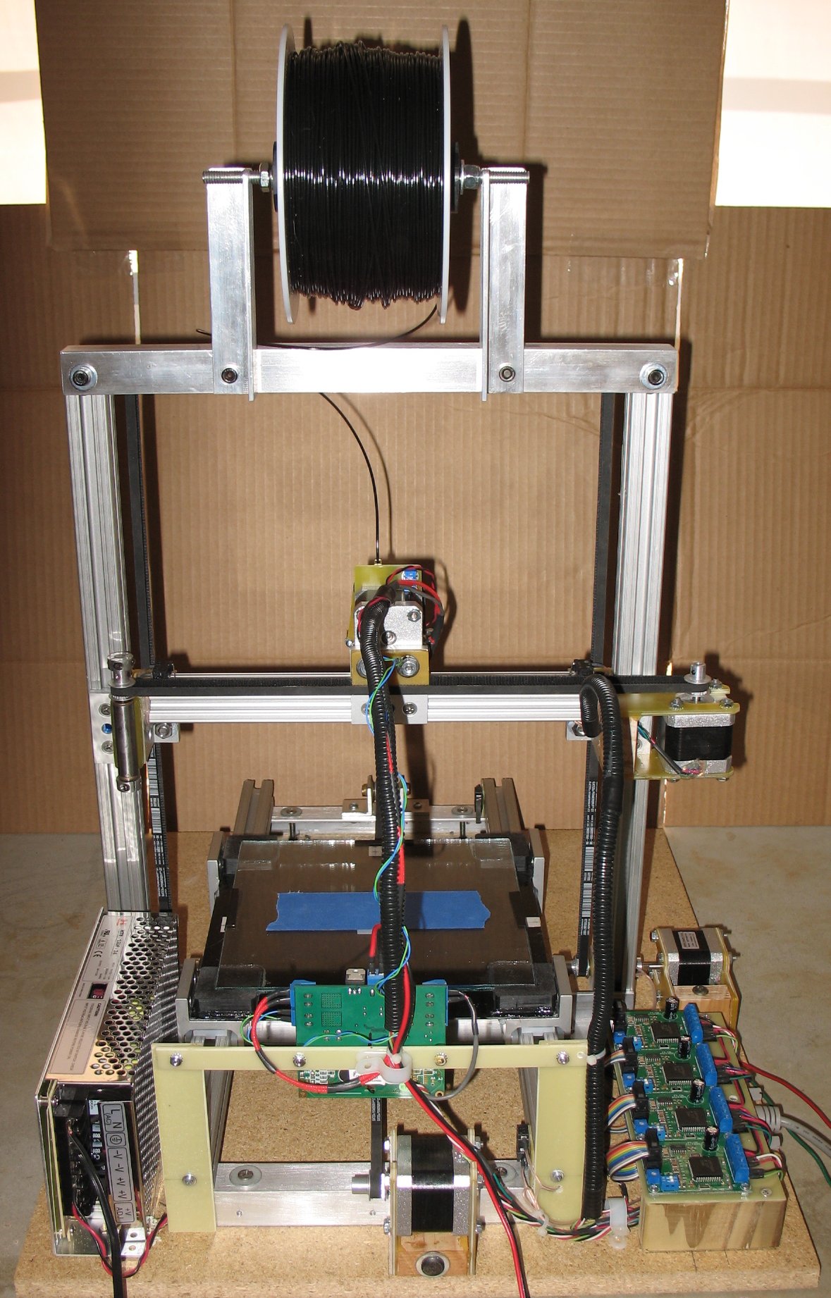
Left: Front view - Right: Rear view The frame, Y-motor, electronics and power supply are screwed down to the board |
|
| - | |
| Click on the images to see a larger image | |
 |
 |
|
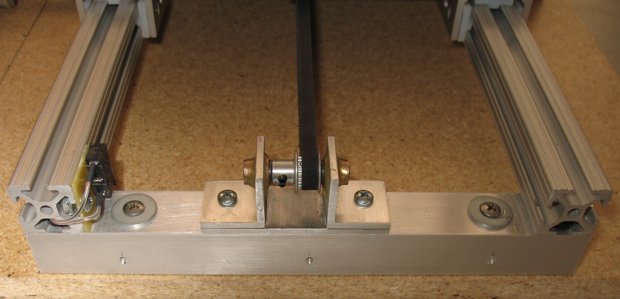
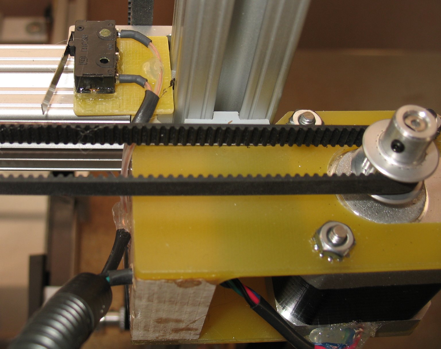
Left: The front end of the Y axis Right: The Y axis belt idler pulley The belt is clamped under the bed in the center The belt is cut at this point and there is a spring attached to a clamp that spans a gap and keeps tension on the belt |
|
| - | |
| Click on the images to see a larger image | |
 |
 |
|
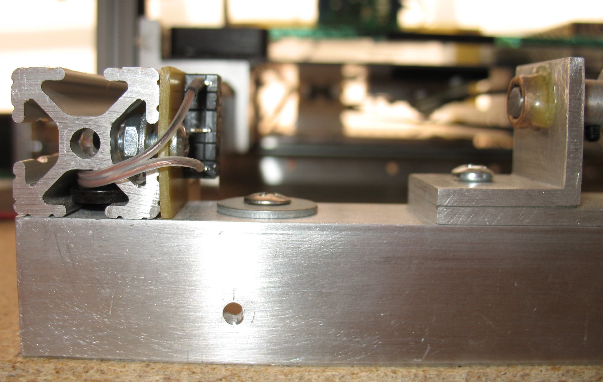
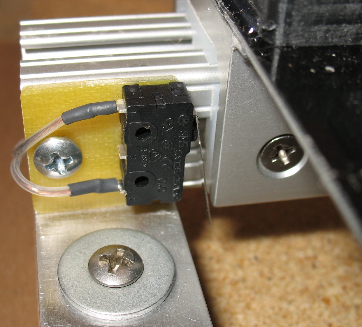
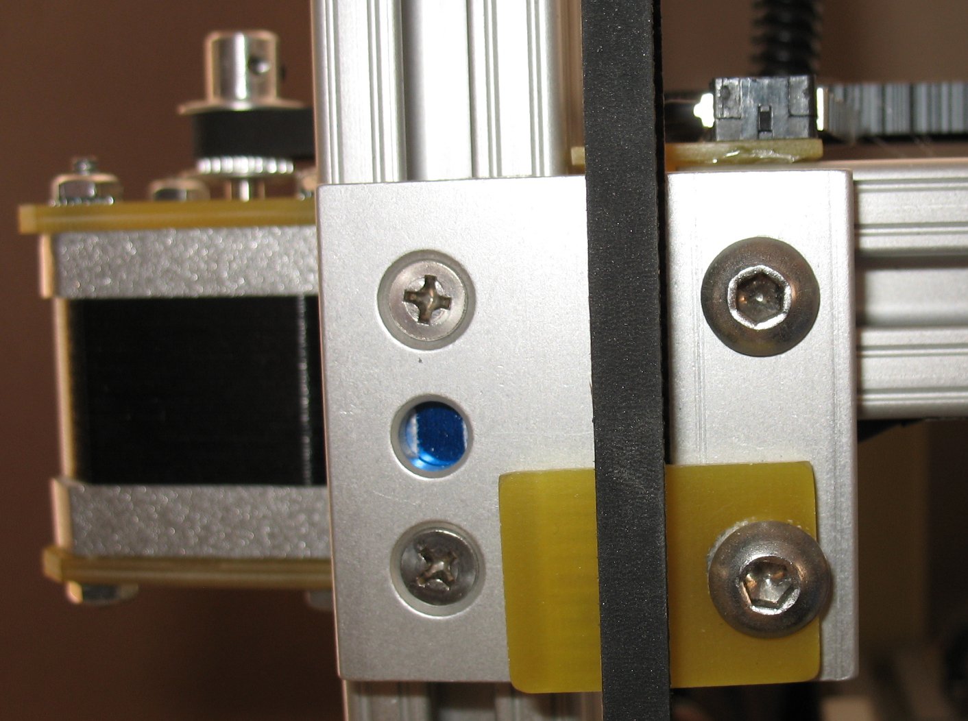
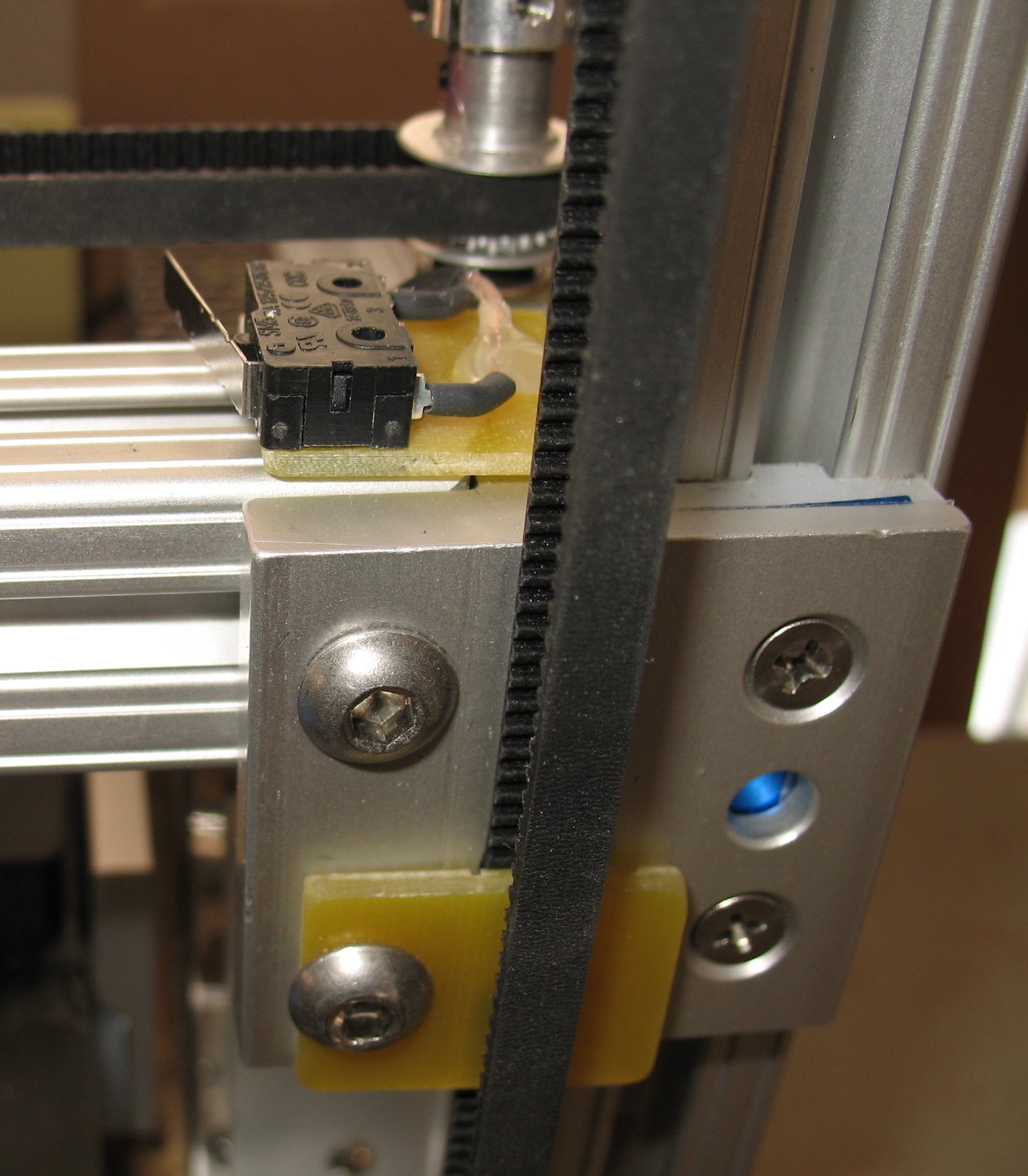
Left: Y axis left side
with limit switch attached to T-Slot Right: Y axis right side The T-Slots are bolted down to 1 inch aluminum angle using T-Slot 1/4-20 nuts and bolts |
|
| - | |
| Click on the images to see a larger image | |
 |
 |
|
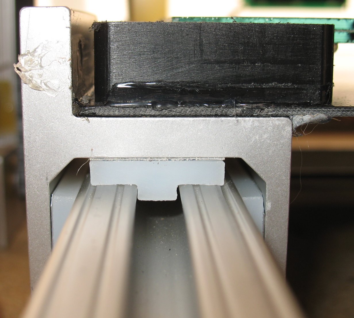
Left: Close up of a limit switch The linear bearings contact the limit switches Right: Close up of a T-Slot linear bearing The bearing material is UHMW-PET The UHMW-PET bearings are screwed onto the bearing blocks .005 inch shims are used behind the bearing material to get the 3 bearings set perfectly on the T-Slots By adjusting all 3 bearings on each bearing block, you can remove all the play and get a smooth sliding bearing It's a bit of work to get these bearings set right |
|
| - | |
| Click on the images to see a larger image | |
 |
- |
|
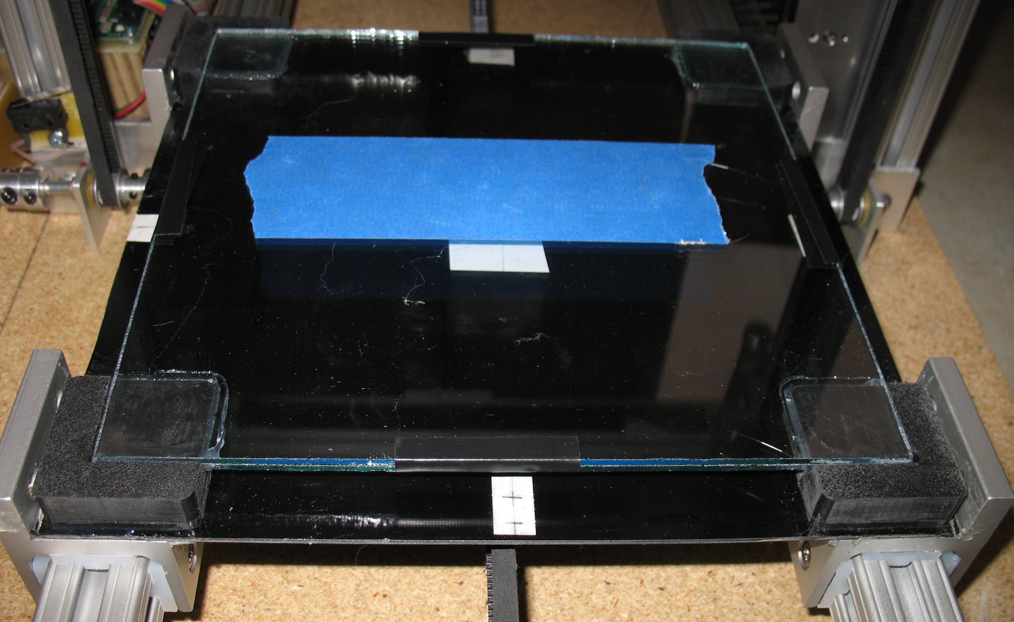
A couple shots of my 3d printer bed I don't have a heater yet but I left room under the glass for a 8 x 8 inch heater The black material is G10 and it is glued to the bearing blocks This method keeps the bearing blocks in perfect alignment because there are no screws forcing it one way or the other The whole bed slides out the end of the T-Slots as an assembly I have two sheets of glass The bottom glass sits on 4 corner blocks and the glass is glued to the 4 corner blocks The top glass can be removed The top glass is leveled by inserting .005 inch shims under each corner I am currently only printing PLA and so a heater is not needed The PLA sticks to the blue painters tape really nice If I want to use ABS, I will have to install a heater |
|
| - | |
| Click on the images to see a larger image | |
 |
 |
|
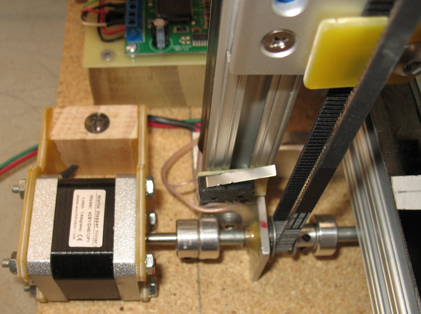
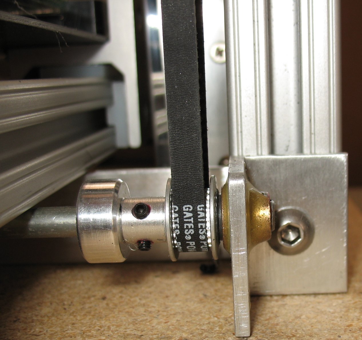
The Z axis stepper motor The motor is coupled to a drive shaft The drive shaft bearings are bronze Oil Lites which are epoxied onto right angle brackets The drive shaft has a GT2 20 tooth pulley on each end There are clamp on spacers next to the pulleys just to give some added support to the pulley The pulleys drive two GT2 belts At the top of the frame is another drive shaft with two GT2 pulleys The belt is clamped onto the Linear bearings of the X axis at each end of the X axis This way, the X axis has two belts pulling it up and down to keep it level and in sync See the images below also |
|
| - | |
| Click on the images to see a larger image | |
 |
 |
|
Left: Another shot of the Z axis stepper motor Right: The other end of the Z axis drive shaft |
|
| - | |
| Click on the images to see a larger image | |
 |
 |
|
Left: Rear view of the 3D printer Right: Rear view of the Y axis stepper motor |
|
| - | |
| Click on the images to see a larger image | |
 |
 |
|
Left: The X axis Right: X axis idler pulley rear view The X axis pulls a T-Slot linear bearing The Extruder is connected to the X axis linear bearing |
|
| - | |
| Click on the images to see a larger image | |
 |
 |
|
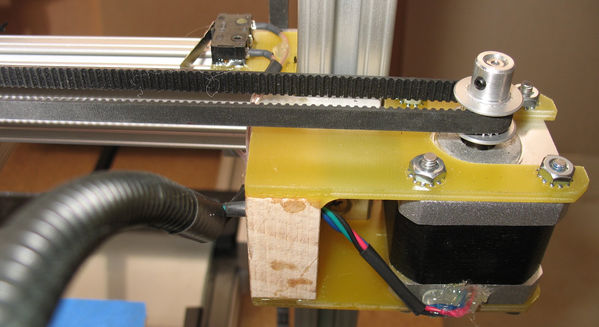
The X axis stepper motor The motor brackets are made from G10 Garolite The motor bracket screw holes are slotted so you can move the motor and set the belt tension The motor bracket is epoxied onto the X axis linear bearings |
|
| - | |
| Click on the images to see a larger image | |
 |
 |
|
GT2 belt clamps with GT2 teeth patterns machined into them I made all the belt clamps on my CNC machine |
|
| - | |
| Click on the images to see a larger image | |
 |
 |
|
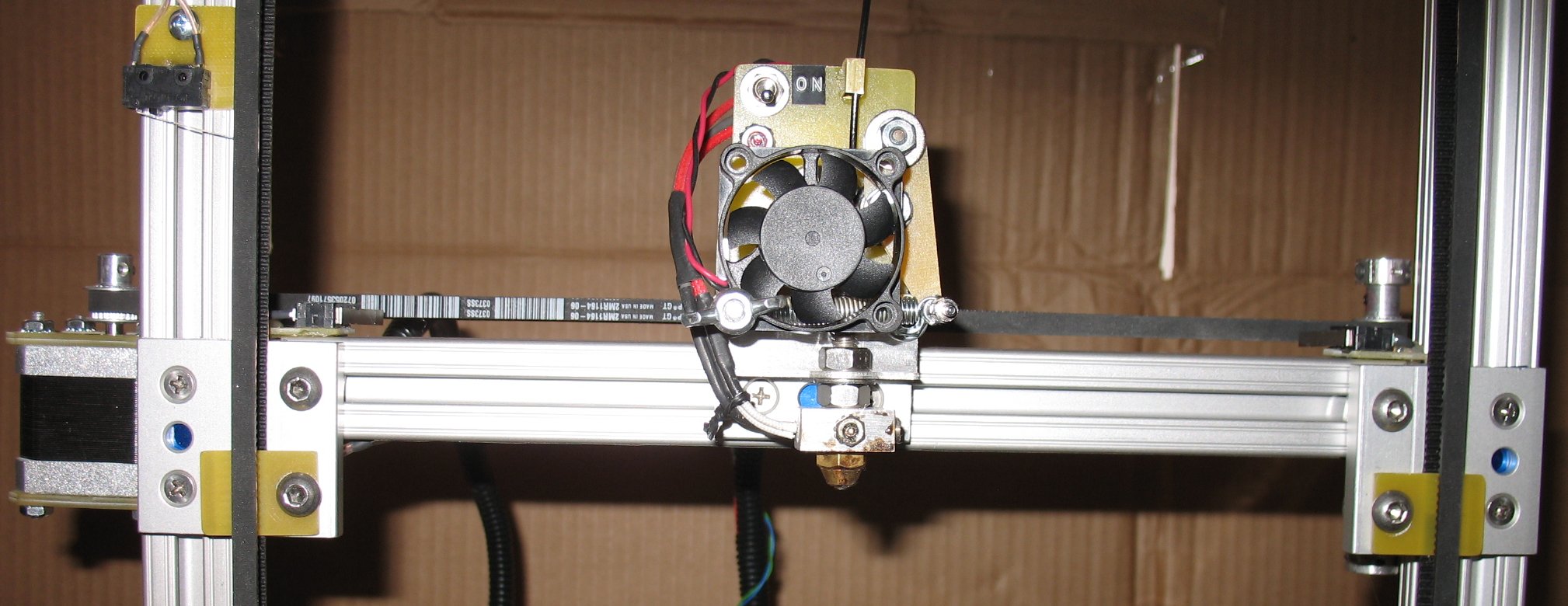
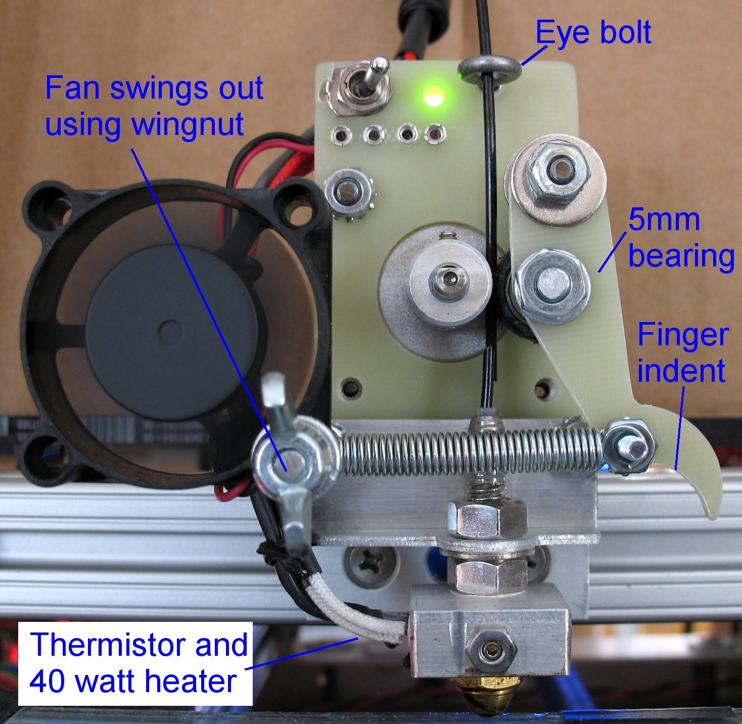
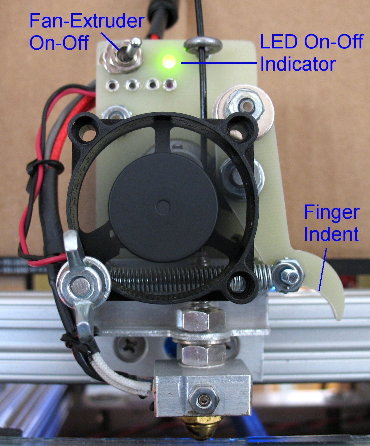
I made the extruder from scratch (See updated extruder info below) I machined the filament gear on my CNC machine There is a spring loaded arm that forces the filament up against the gear The spring loaded arm has a 5mm sealed bearing with a plastic grooved outer rim I added a finger indent to make pulling the spring loaded arm out of the way to load filament The switch at the top turns on the 40 watt cartridge heater and the fan I added a LED to indicate when the extruder heater is on I added an eye bolt that aligns the filament with the filament gear and idler rrm The 40mm fan swings out of the way by loosening a wing nut The fan cools the Stainless Steel delivery tube at the top end The SS delivery tube has a PFTE sleeve inside to keep the filament from touching the insides of the SS tube There is a thermistor on the hot end A Gnex temp control board reads the thermistor on the hot end and keeps the temperature steady 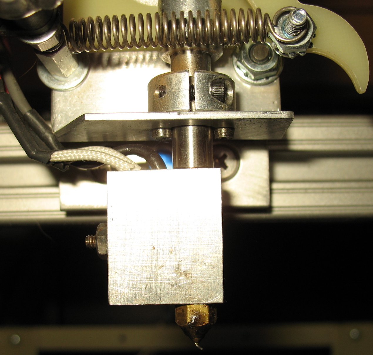 UPDATE: I updated the extruder to a new design and it works really well It has a vertical heater block with a stainless steel delivery tube Inside the tube is a thick PFTE tube The filament is protected from heat until it reaches the hot end The 40 watt heater cartridge and Thermistor are inside the aluminum block There is a set screw and a nut on the left side that clamps the heater cartridge in place You can the wires on the left side of the stainless steel tube The brass nozzle is a .39 Makerbot style nozzle |
|
| - | |
| Click on the images to see a larger image | |
 |
 |
|
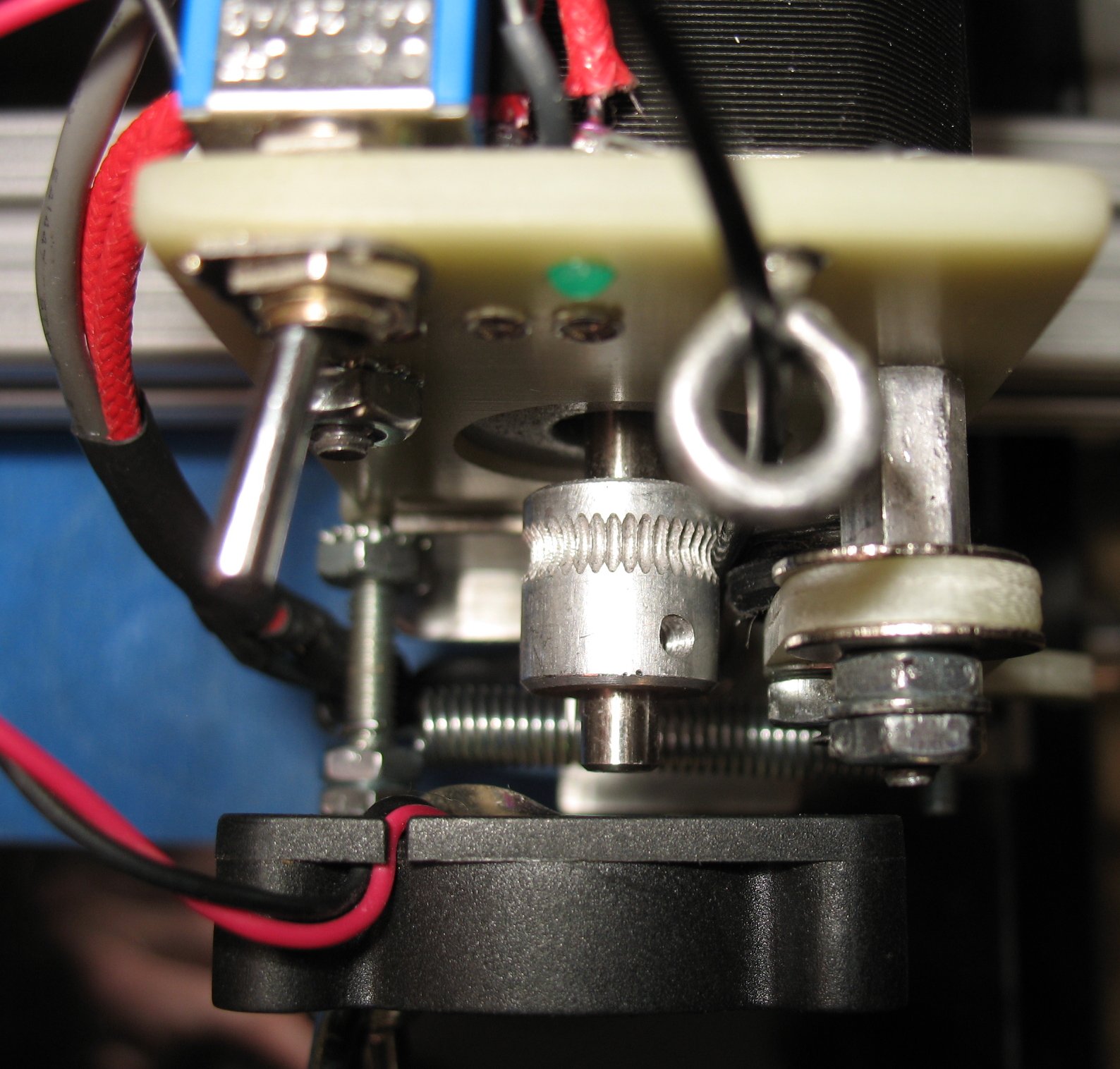
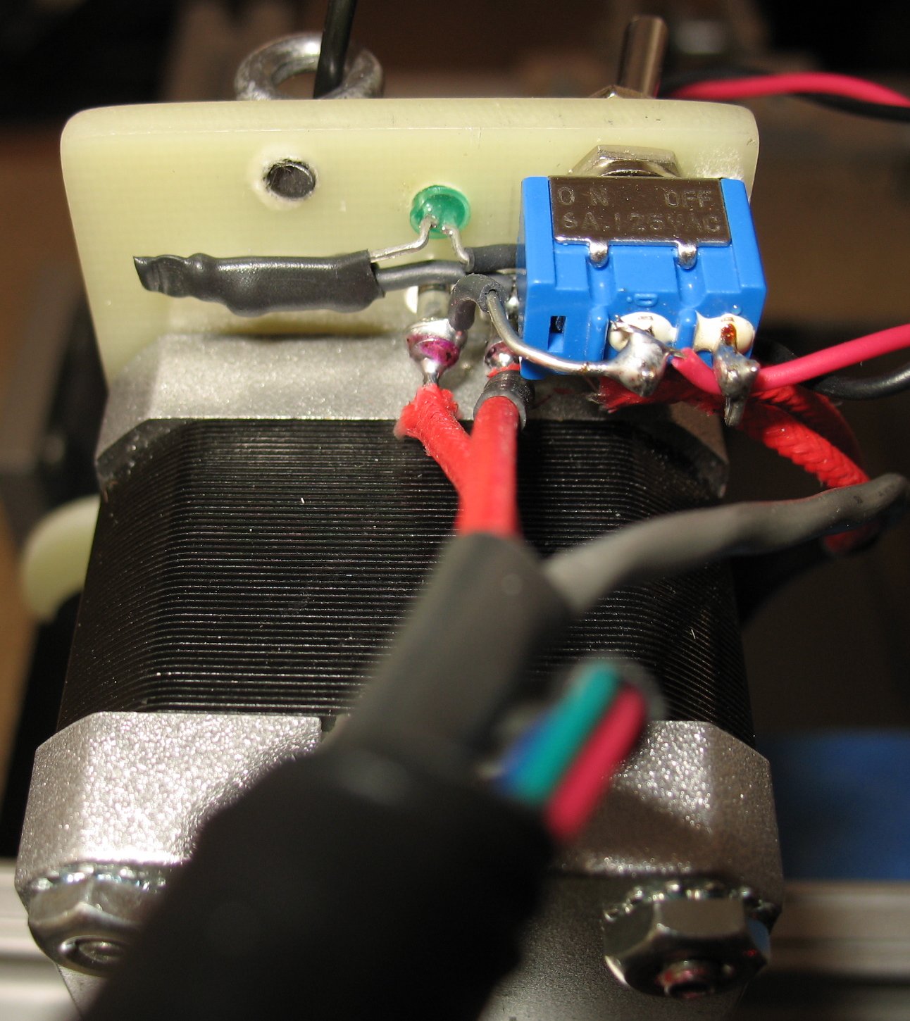
Left: Top view looking down on the extruder You can see the toothed pattern I cut into the filament drive gear using my CNC machine Right: Rear view of the extruder switches and LED |
|
| - | |
| Click on the images to see a larger image | |
 |
 |
|
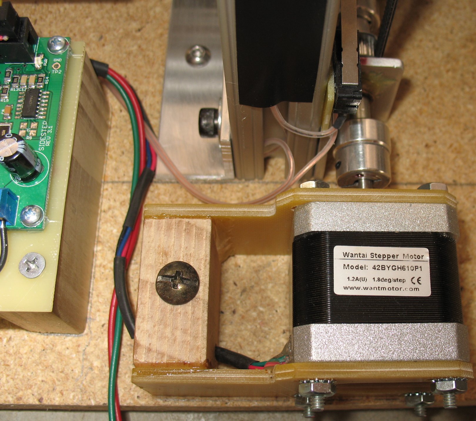
Left: The Probotix driver boards and power supply Right: Probotix side step driver boards Under the driver boards is a Probotix parallel port breakout board Mach3 uses a parallel port to drive the motors and control items like spindles, cooling misters, etc. I also have a touch probe that can touch down on the bed surface and zero out the Z axis Links to my Probotix Electronics Probotix SideStep Stepper Motor Driver Probotix PBX-2 CNC Parallel Port Breakout Board Probotix Power supply Probotix kit with all these items plus cables |
|
| - | |
| Click on the images to see a larger image | |
 |
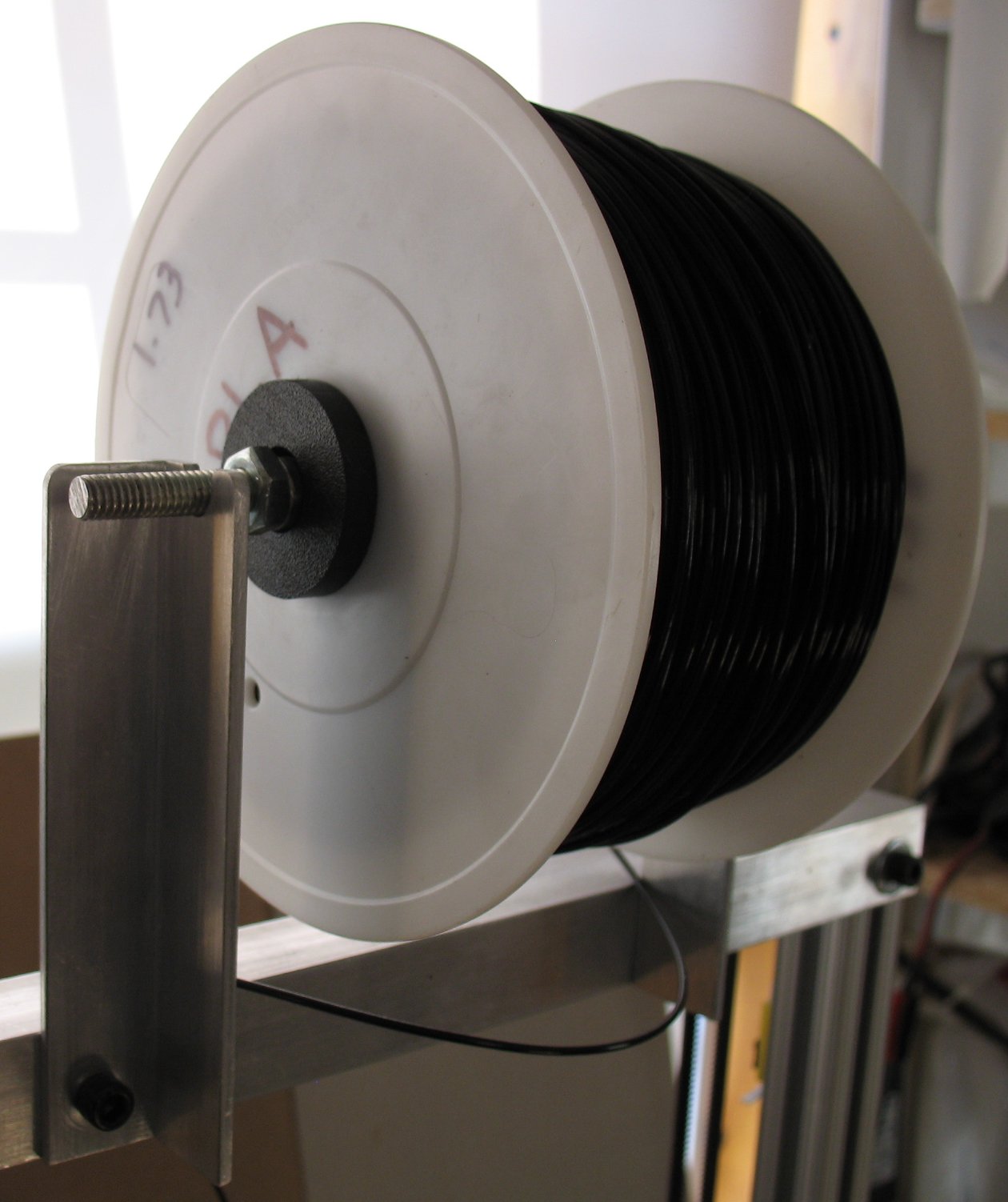 |
| Left: The Gnex dual temperature control board. This board can control the extruder and a bed heater Right: The ball bearing mounted filament spool support Inside there are two 1/4 inch sealed ball bearings so the spool turns very easily |
|
| - | |
| Click on the images to see a larger image | |
 |
 |
|
08/06/2013: Here are some up to date images of the printer I will be offering this printer for sale as it is shown in the two images above I have two printers now and only room for one I removed the Stepper motor drive boards and used them on my 2nd printer build I also removed the Gnex temp control board for printer #2 build I will be selling this printer for just the parts cost and no labor cost I have over $500 in parts in this printer I have many hours of labor in this printer build I would guess it took 40+ hours to design and build from scratch I printed many of the parts for printer #2 with this printer It is a working printer, all you need is the stepper drivers - electronics boards , a power supply and some 1.75mm PLA filament If you want to use ABS filament, you would have to add a heater to the bed The bed surface area is 9 x 9 inches so you can add a 8 x 8 inch bed heater The Y axis travel is 8.25 inches The X axis travel is 8 inches The Z axis travel is 10.25 inches The linear bearings are adjusted via small screws on 3 sides of each bearing You should not have to adjust them very often because the UHMW plastic does not wear I use pure silicon spray on the T Slots to make the bearings slide really nice You can get spray silicon at Wal-Mart I use Mach3 to control this printer and that is way different than what most Reprap people use I am not at all familiar with any of the electronics that the Reprap crowd uses I can't offer any technical assistance in getting this printer up and running You need to have the basic knowledge of how the electronics work All the wires are ready to be connected I just unhooked all the wires and took my electronics off The wires to be hooked up are 4 Nema 17 motors - 4 wires each motor 6 limit switches - X Y Z axis are in series - 2 wires each axis x 3 axis = 6 wires 40 watt 12 volt hot end heater - 2 wires Thermistor - 2 wires 40mm 12 volt Fan - 2 wires Here's a list of the parts I used and my cost  |
|
| - | |
Enter My Tube Amp Parts Store Here
Mobile users Enter My Tube Amp Parts Store Here
The Tube amp Library of information
Click the link above for Tube amp info, Schematics, Board building information, Projects, Mods, Transformer diagrams, Photo's, Sound clips.
There are hundreds of pages of Tube amp information on my library page.
Please visit my Tube Amplifier Forum
Here's the place you can go to ask tube amplifier questions.
You will find a large community of friendly amp builders at the link above.
Check the huge library of Schematics here
Design your own custom Turret Board or Eyelet board
DIY Layout Creator file analyzer program
DIY Layout Creator file library
How to email me
|
MEMBER OF PROJECT HONEY POT Spam Harvester Protection Network provided by Unspam |