
Relay information page |
Hookup info for my Single Relay and Relay Power supply boards |
| The parts shown on this page can be found here in my catalog pages Channel switching page Screws Nuts and Washers page Short Turret lugs are on this page Capacitors page Kits-Parts list page is here - Everything in a kit |
| Click on the images to see larger images |
|
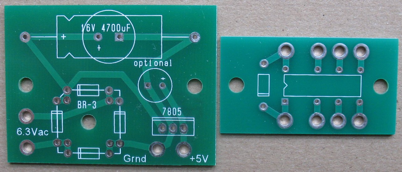
| Left: Relay Power supply board - Right: Single relay board Note that the power supply board can use a Radial or Axial 4700uf cap |
| - |
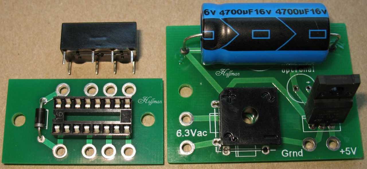 |
| Left: The single relay board with the relay socket and 1n4001 diode mounted Right: The relay power supply board with the parts mounted See the link at the top of this page for a link to all these parts in my web store The 4700uf axial cap shown in this photo is no longer available. I now stock a 4700uf Radial cap for the power supply board See the image below |
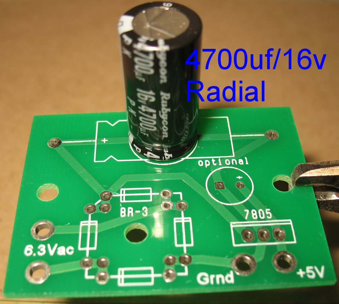 |
| This is the 4700uf Radial cap used on the power supply boards |
| - |
 |
|
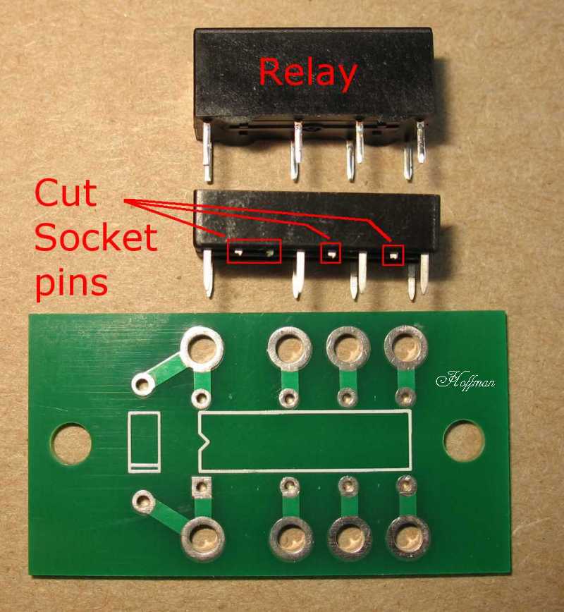
Relay Board Assembly Tips: The single relay board only has the 8 holes that match the 8 relay pins The relay only uses 8 of the 16 pins on the 16 pin socket When using the 16 pin relay socket I sell, clip off the pins that are not used On some sockets you can just push out the pins you want to remove You can solder the relay directly to the board without a socket. This makes it harder to change the relay if there is ever a failure The socket makes it easier to remove the relay from the board The large holes with the silver rings are the wire hookup holes You can solder wires directly to those holes or, you can mount a short turret lug in the holes If you use the short turret lugs I sell, you do not have to swage them onto the board. You can actually solder them to the board This makes it easier if you do not have a turret lug swaging tool |
| - |
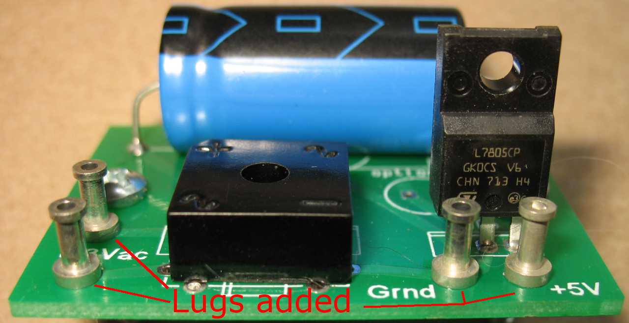 |
| I added and soldered these four lugs to the power supply board. You don't have to use turret lugs, you can solder wires directly to the holes on the board |
| - |
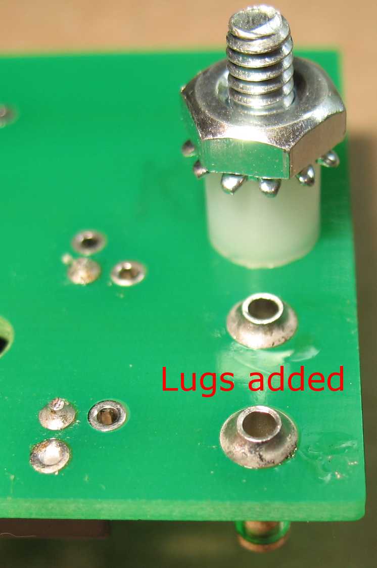 |
| Here's a shot of the soldered on lugs I added to the power supply board. It's way easier to solder them than to swage them Tip: Add these lugs first before the other parts. You can tip the board upside down on the bench and it will hold the lugs in place while you solder them See the customer tip below |
 |
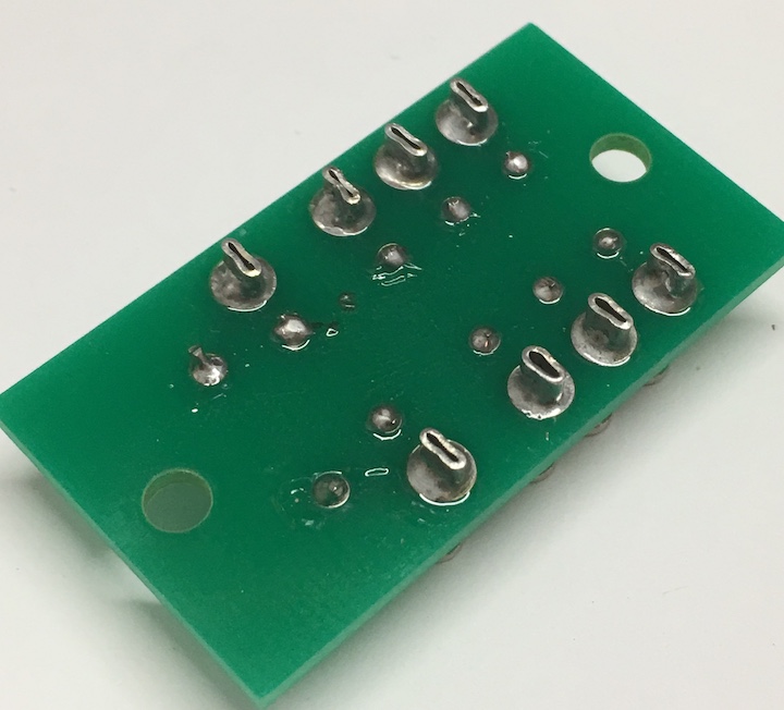 |
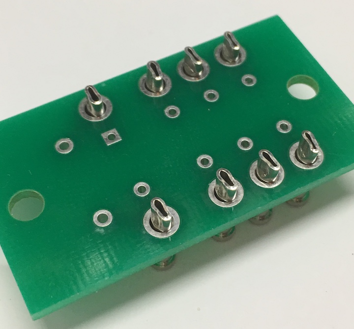
| Here's a tip from one of my customers. He noted that the soldered lugs will move around when trying to solder wires to them He crimped the lugs first and then soldered them See the two images above |
| - |
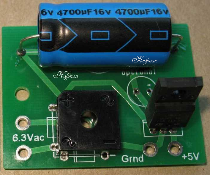 |
| Relay Power supply assembly Tips: The image above shows the relay power supply board populated with parts. You can use a 50 volt bridge rectifier or 4 individual 1n4001 diodes. The board has holes for both methods There is a 7805 5 volt voltage regulator. Note that the regulator can supply up to 1.5 amps of DC current The relays I sell only use 40 milliamps of coil current In Theory, you could supply 37.5 relays with this power supply board 1500 milliamps / 0.04 milliamps = 37.5 The filter cap is a 4700uf/16 volt capacitor The axial cap shown in the image is no longer available I now stock a 4700uf Radial cap for the power supply board See the image on this page of that cap There is an extra spot on the board for a small radial filter cap, but it is not needed |
| - |
|
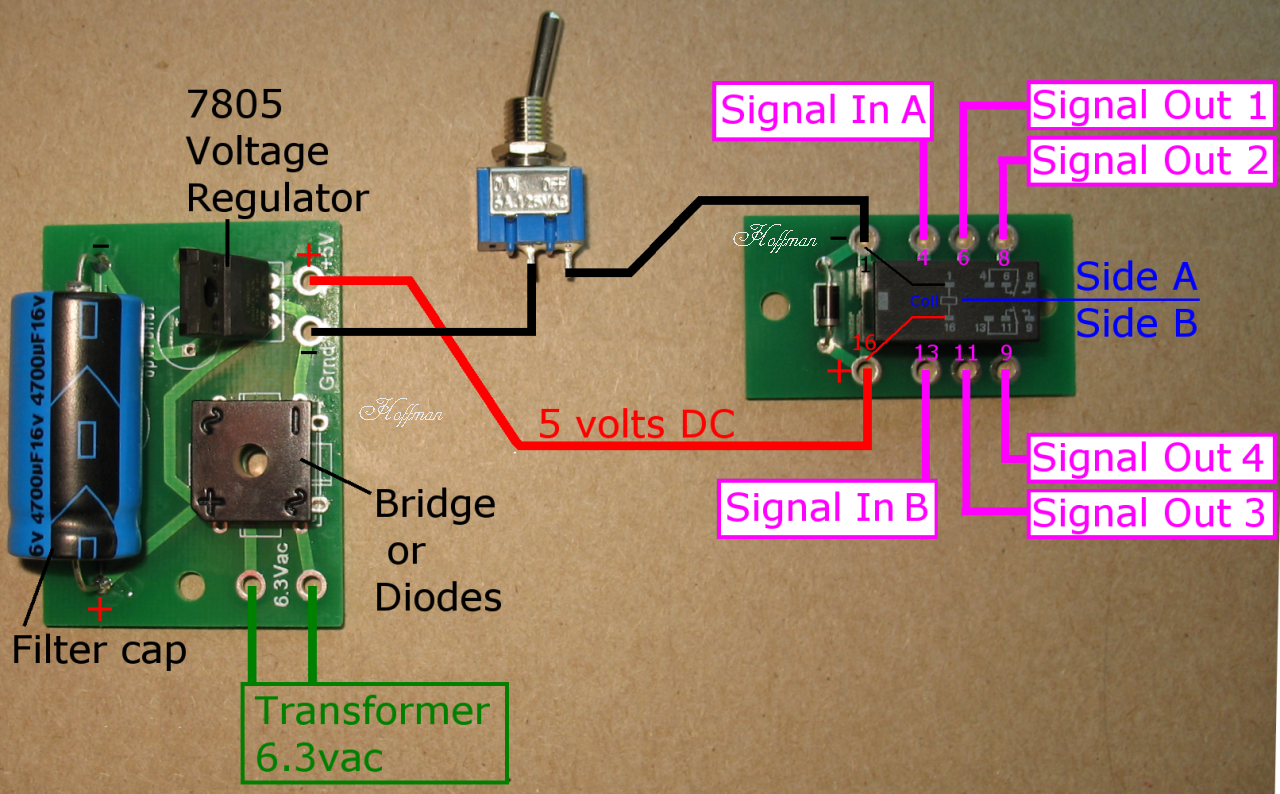
| Hookup Diagram Power supply board The two 6.3 vac hookup points go to your amps 6.3 vac heater wires The +5 and GND connections go to the relay board coil + and - connections These are the Red and Black lines on the diagram above You can have a simple SPST switch interrupt the Black DC minus wire to turn the relay coil on or off You could also use an external foot switch to do this Relay board There is a 1n4001 diode across the relay coil to prevent kickback into the circuit when the coil disengages The relay has two separate switching halves. Side A and Side B in my diagram above You could switch two separate signals at the same time, or you could do something like switch an extra gain stage in and out like I do on this page Hotswitch mod page info In my diagram above, when the relay coil is engaged or disengaged, Signal In A goes to either Signal Out 1 or Signal Out 2 Signal Out 1 is the normally closed contact for Side A Signal In B goes to either Signal Out 3 or Signal Out 4 Signal Out 3 is the normally closed contact for Side B Important note: Do not use the metal amp chassis as the DC minus wire Run two separate wires from the relay power supply board to the relay board. If using an external foot switch, make sure the chassis jack where you plug in the foot switch is isolated from the chassis. If you use a plastic jack, like a Marshal style jack, you will be good to go If you use a Switchcraft metal jack, you must use isolation washers so that the jack is not in contact with the metal chassis I stock Shoulder washers for Switchcraft jacks on this page Misc. Hardware Page |
| - |
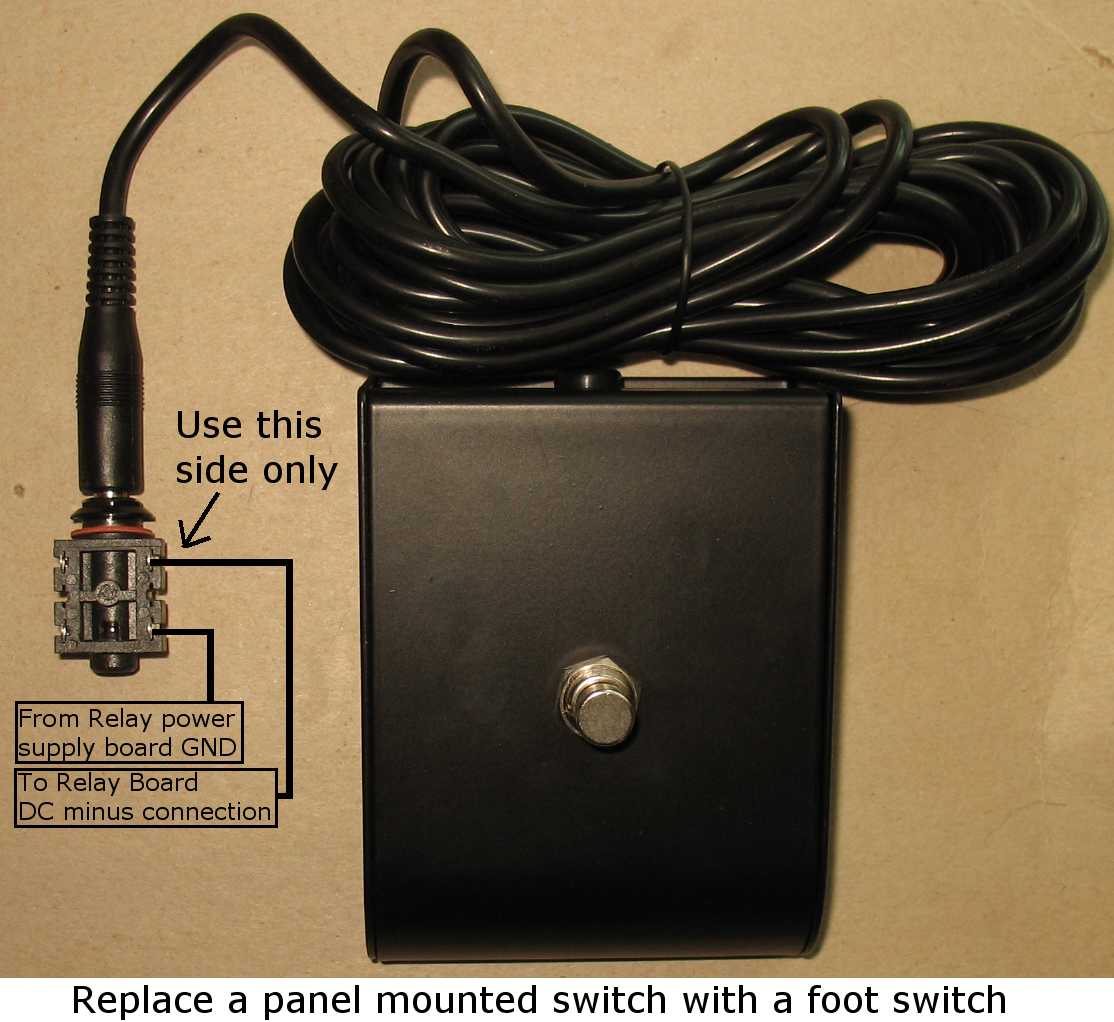 |
| If you wanted to control the relay with a foot switch, just replace the SPST toggle switch with this
configuration I stock foot switches on this page I stock Jacks on this page |
| - |
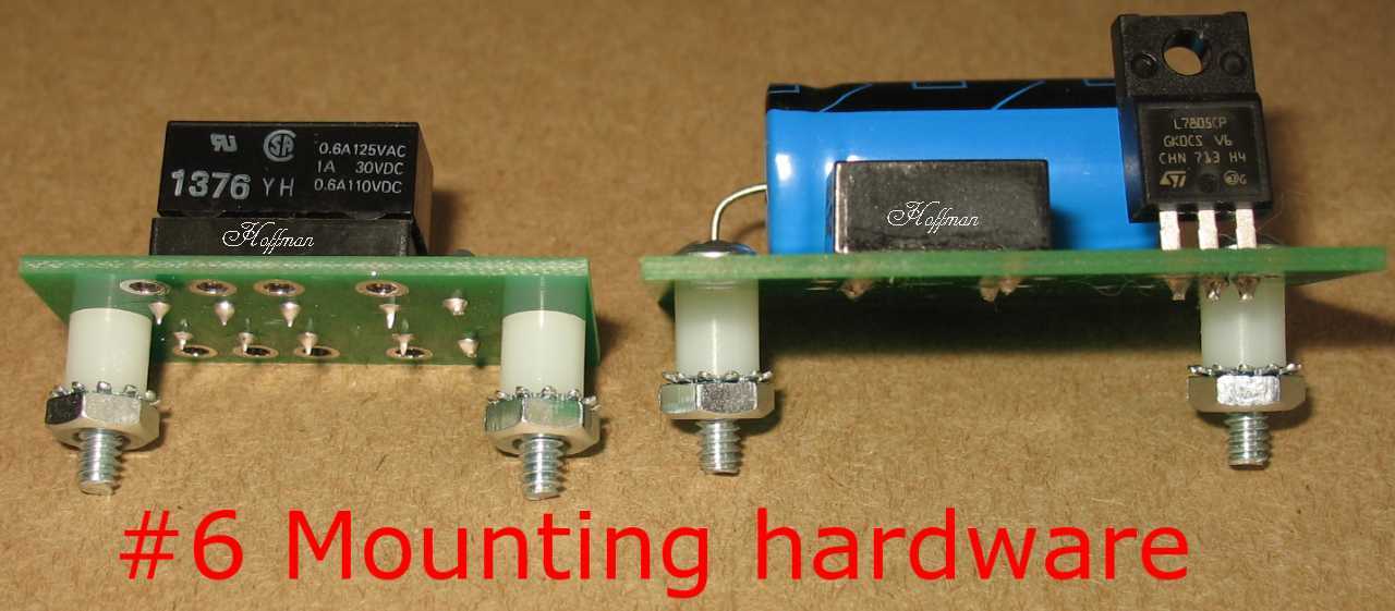 |
| You use #6 mounting hardware to mount the boards inside the amp This mounting hardware is included on the Parts List-Kits page |
| The parts shown on this page can be found here in my catalog pages Channel switching page Screws Nuts and Washers page Short Turret lugs are on this page Capacitors page Kits-Parts list page to get everything in a kit |
Enter My Tube Amp Parts Store Here
Mobile users Enter My Tube Amp Parts Store Here
The Tube amp Library of information
Click the link above for Tube amp info, Schematics, Board building information, Projects, Mods, Transformer diagrams, Photo's, Sound clips.
There are hundreds of pages of Tube amp information on my library page.
Please visit my Tube Amplifier Forum
Here's the place you can go to ask tube amplifier questions.
You will find a large community of friendly amp builders at the link above.
Check the huge library of Schematics here
Design your own custom Turret Board or Eyelet board
DIY Layout Creator file analyzer program
DIY Layout Creator file library
How to email me
|
MEMBER OF PROJECT HONEY POT Spam Harvester Protection Network provided by Unspam |