
| Back to Library page |
Gain stage mod added to stock circuit |
| Here is a link to my relay switching info page |
Note: This is not a channel switching mod. The volume difference between the switch off and switch on is very large. You will probably end up just leaving the mod switched on all the time once you hear how cool it sounds. This mod is here for information purposes only. I do not offer technical support on how to install it in your amp. You have to be able to figure it out from the drawings below. You will be using the 2nd half of V1 as a gain stage. I have converted the 2nd volume pot into a master volume because it is very handy. The mix or combination of the volume and master makes the amp have tons of different tones. I have re-voiced the first half of the V1 to not be a super bass. You will need a good quality DPDT toggle switch or a high quality DPDT signal switching relay, 2 x 2.2k 1/2 watt resistors, 2 x 470k 1/2 watt resistors, 2 x .022/630v caps and some shielded cable. You can mount the DPDT toggle switch on the front panel in one of the old input jack holes. Or you can use the switch to toggle the relay. Keep all the wire leads as short as possible. The 470k resistor connected to the end of the .022 sets the gain level that you send to V2 pin 2. When the toggle switch or Relay is off, the gain stage is switched completely out of the signal path and you are back to a stock pre-amp. Note that when the gain stage is switched off, V1 pin 7 input grid is connected to ground to shut off the right half of the tube. |
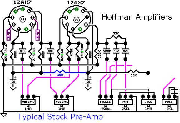 |
| This is a typical vintage Marshall circuit. It has two channels of input on V1 that blend together and go to V2 |
| - |
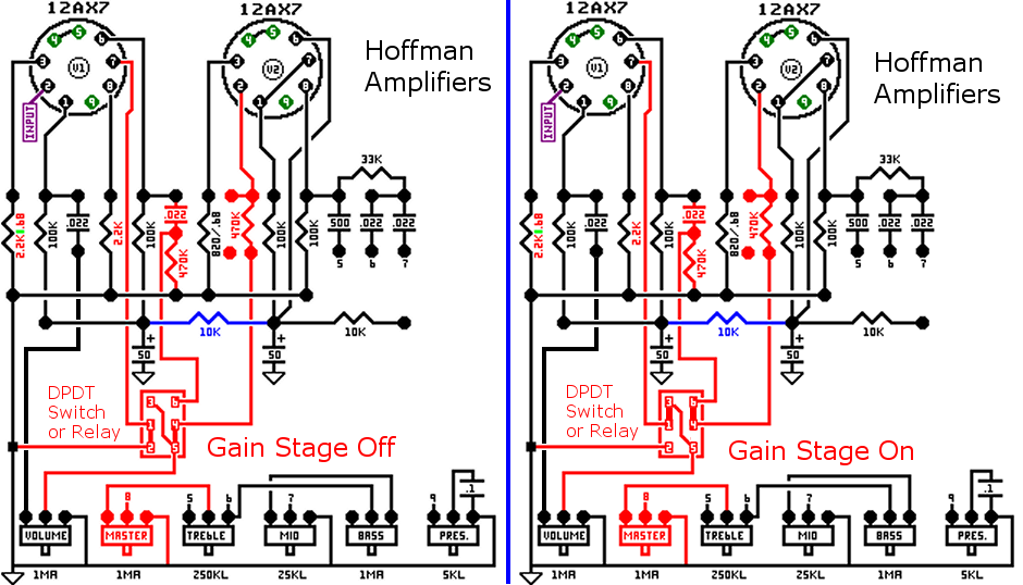 |
| The areas in red are new or have changed from the stock layout shown up above Here's what the circuit looks like after adding a switch or relay to switch in an extra gain stage. V1 right half will now be gain stage 2 You can follow the connections on the diagram above to see how the connections are made through the switch or relay Left - Gain Stage Off: The gain stage is switched out of the circuit V1 left half signal leaves the .022 cap, goes to the left hand volume control Then through the switch and onto the 470k resistor on V2 pin 2 (in 5 - out 4) V1 pin 7 is grounded which shuts off V1 right half (in 1 - out 2) Right - Gain Stage On: The gain stage is switched into series between V1 and V2 V1 left half signal leaves the .022 cap, goes to the left hand volume control It then goes through the switch and onto V1 pin 7 (in 5 out 1) The signal leaves V1 right half and goes back to the switch (in 6) It then leaves the switch and goes to the 470k resistor on V2 pin 2 (out 4) You have now added another gain stage in series between V1 left half and V2 Note that the volume level will jump way up and so it is not a good idea to use this like channel switching |
| - |
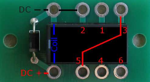 |
| If you are using one of my single relay boards, this image shows the hookup diagram switch numbers as they relate to the relay board holes |
| - |
| Here is a link to my relay switching info page |
| - |
Enter My Tube Amp Parts Store Here
Mobile users Enter My Tube Amp Parts Store Here
The Tube amp Library of information
Click the link above for Tube amp info, Schematics, Board building information, Projects, Mods, Transformer diagrams, Photo's, Sound clips.
There are hundreds of pages of Tube amp information on my library page.
Please visit my Tube Amplifier Forum
Here's the place you can go to ask tube amplifier questions.
You will find a large community of friendly amp builders at the link above.
Check the huge library of Schematics here
Design your own custom Turret Board or Eyelet board
DIY Layout Creator file analyzer program
DIY Layout Creator file library
How to email me
|
MEMBER OF PROJECT HONEY POT Spam Harvester Protection Network provided by Unspam |