
Installation Instructions for all Hoffman boards. |
|
| WARNING: DO NOT WORK ON ANY AMPLIFIER WITH THE AC PLUG PLUGGED INTO THE WALL SOCKET! ALWAYS DISCHARGE THE FILTER CAPS BEFORE WORKING ON AN AMPLIFIER! IF YOU ARE UNSURE OF HOW TO DO SOMETHING PLEASE TAKE IT TO A TECHNICIAN! |
|
| Note that Hoffman boards are not assembled by looking at my builds. I do test builds first and change the designs based on those builds. You assemble Hoffman boards using the documents listed under each board on the library page here Hoffman Tube Amp Library Page Hoffman Turret board Installation instructions These instructions are not specific to any one of the Hoffman Turret boards. The builds are pretty much the same for all of them This document describes the process that is used to install all my turret boards Make sure you look at every document on the library page for the board you are building The layout diagram and schematic are in one PDF file The Bill of materials - BOM - is in another PDF file Layout Diagrams, Schematics, BOMs and build pictures are located on this page Check out all these helpful building links These links will open in a new window Important - hookup notes for all Hoffman Boards Grounding information page Filter cap hookup solutions Bassman Re-Issue filter cap hookup info How to use my turret lug tool How to install turret lugs using a drill press How to lace up and solder turret lugs Choosing a chassis for a amp project Scratch building amp info Follow along with the instructions below by printing out your layout diagram Have your layout diagram in front of you so you can reference it |
|
| Click on the image below to see a larger image | |
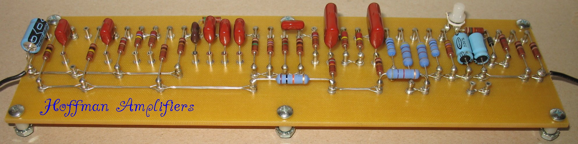 A Hoffman Turret board |
|
This is the order of events on how I build amps from scratch (1) Install and wire up all the basic infrastructure connections (2) Install the board with no parts on the board (3) Install the pots and input jacks (4) Install the parts on the board (5) Wire up the pots to the board (6) Turn on the amp, bias the power tubes and enjoy The events above are all explained further down this page |
|
| - | |
| Click on the image below to see a larger image | |
 |
|
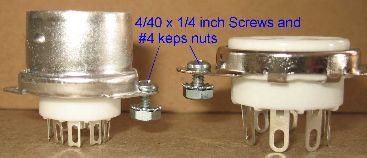
| I use 4/40 x 1/4 inch long screws and #4 Keps nuts to mount the tube sockets Some tube sockets have undersized mounting holes These need to be drilled out a bit larger for #4 screws Use a 7/64 inch drill bit for #4 screws |
|
| - | |
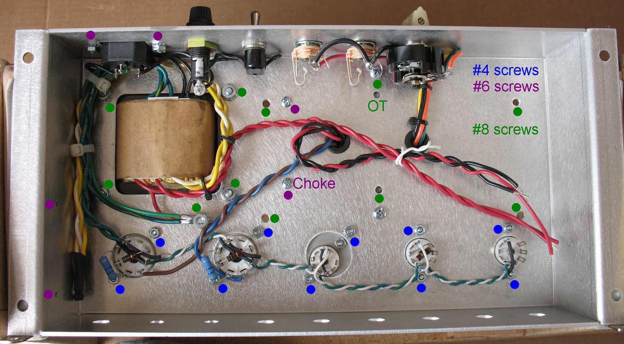
| Screws and Nuts information #4 screws are .108 inches in diameter - Use a 7/64 inch drill bit #6 screws are .132 inches in diameter - Use a 9/64 inch drill bit #8 screws are .158 inches in diameter - Use a 11/64 inch drill bit #10 screws are .186 inches in diameter - Use a 13/64 inch drill bit I stock screws, nuts and washers on this page Screw uses for common chassis and parts holes Use #4 screws to mount tube sockets Use #4 screws for tube socket adapter plates Use #6 screws for capacitor clamps Use #6 screws for IEC receptacles Use #6 or #8 screws for chokes Use #6 screws for small output transformers Use # 8 screws for Large Output transformers Use #8 screws for Power transformers Use 8/32 x 5/8 inches long screws for your main ground screw by the power transformer Use 8/32 x 5/8 inches long screws to mount the boards when using 1/4 tall standoffs Use #10 screws and Rivnuts to mount the chassis Use oversized fender washers to clamp something to get a larger clamping area See the image below for color coded screw info |
|
| Click on the image below to see a larger image | |
 |
|
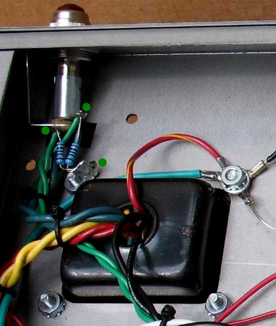
| I do all the basic wiring first before installing the board. This includes the filament wires if they are going to be laying down flat on the chassis like in the photo above. The power transformer in this image has a filament center tap wire connected to ground (green with yellow stripe) If you are flying your filament wires overhead, like a Fender, you can do the filament wires later in the build You can see in the picture above that I have already drilled the mounting holes for the Turret board I like to use 18 gauge stranded wire for the fuses, switches and speaker connections Tip: Install tubes into the tube sockets before you start wiring the tube sockets This will keep the tube socket pins aligned straight as you solder wires to the sockets If you wire up all the sockets without doing this, it may be difficult to get a tube into the socket later |
|
| - | |
|
Infrastructure Wiring: See the links at the top of this page for other important amp building info Plan out where the board will go and drill all those holes first. Taking into consideration where the transformers will be mounted and anything else that may interfere with the board mounting screws. See the detailed info further down the page for details on mounting your board in a chassis Install all the transformers, switches, fuse holders, speaker jacks, tube sockets and wire all of them up. I install the filament wires onto the tube sockets at this point if the filament wires lay down flat on the chassis. If the filament wires fly overhead, you can do them later On the Output transformer, if you are not sure which plate wire goes to which plate, leave the wires full length for now so you can reverse them later if they are not correct Any wire that is not connected to the turret board (except pot wires) can be wired up at this point Connect the main ground wire at the power transformer end of the board to the chassis ground screw. If the power transformer has a HT center tap, connect that wire to the chassis ground screw If your power transformer has a filament center tap, connect that to the chassis ground screw |
|
| - | |
|
See this common hookup info PDF file for diagrams on filament hookups - Common hookups document See the links at the top of this page for other important amp building info Filament wiring: You can run the green filament wires a couple different ways In the picture below, you can see that they go to the fender lamp assembly first, and then they go to the last power tube socket If you do not have a Fender style lamp assembly, you can run the green wires right to the last power tube socket From the last power tube, run a twisted pair of filament wires all the way down to the first preamp tube If your power transformer has a filament center tap wire, (usually green with yellow stripe) crimp and solder on a ring terminal and then clamp that wire to your main chassis ground point If your power transformer does not have a filament center tap wire, you will have to use two 100 ohm resistors as an artificial center tap. Some of my turret boards have two 100 ohm resistors on them and some do not. If your board does not have two 100 ohm resistors, and you have a Fender style lamp assembly, you can solder the two 100 ohm resistors to the lamp terminals. Then twist the other ends together and connect that end to ground using a round ring terminal Bolt the ring terminal to the nearest power transformer lug, or add some wire to the twisted together end and go to your main ground lug. |
|
| Click on the image below to see a larger image | |
|
|
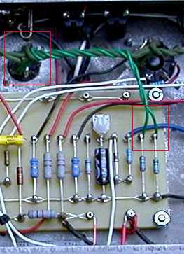
| In the image above, the green filament wires go to the lamp assembly first and then to the last power tube The two 100 ohm resistors go to each terminal on the lamp and then they are twisted together and go to a ground lug |
|
| - | |
 |
|
| The picture above shows the two 100 ohm resistors on the board hooked up to the main filament string If your board has two 100 ohm resistors on it, solder a green wire from each 100 ohm resistor, twist the wires into a nice twisted pair, then go to the nearest tube socket. Solder the twisted green wires to the filament connections on the back of the tube socket Power tubes usually have more room to add wires and so I usually use a power tube socket to connect to the two 100 ohm resistors |
|
| - | |
| Filter cap hookups: Look at the layout diagram to see where each filter cap should be connected on the board. Wrap the wire around each turret lug and solder it. The filter cap grounds should technically be connected as close as possible to the cathode of the tube that they go to, but this is usually not possible. In Fender style amps, the filter caps are in a cap can on the back of the amp. You can use a cap can if you want to or install them inside the amp chassis. In Marshall type amps, each cap is grounded to the chassis and flows through the chassis back to the main transformer ground lug. On multi can caps there is only one ground wire for the whole cap and several positive wires that will go to the board Connect the high voltage wires from the power transformer to the rectifier. You could have a tube rectifier or diodes on the board, it depends on the amp circuit. Look at your layout diagram for specific hookup info If your amp uses a choke, connect the choke from the B+ to the next lug on the power rail to bridge the gap between B+ and the screens. Look at your layout diagram for specific hookup info Filter caps can be inside the amp or on an external cap board I have several documents in the library that have filter cap info Filter Cap Solutions Re-Issue Bassman Cap document Common Hookups Document |
|
| - | |
| Click on the image below to see a larger image | |
 |
|
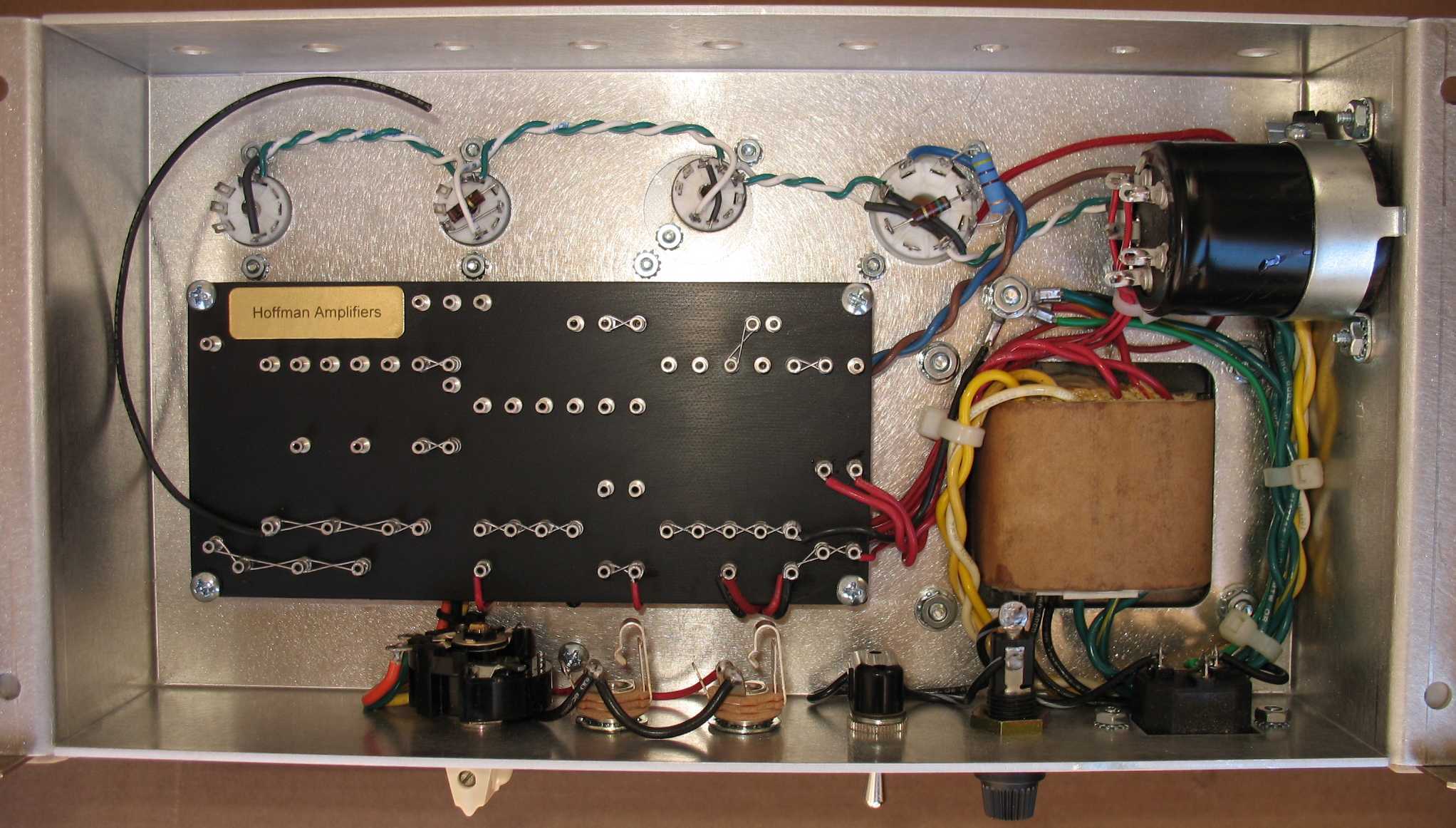
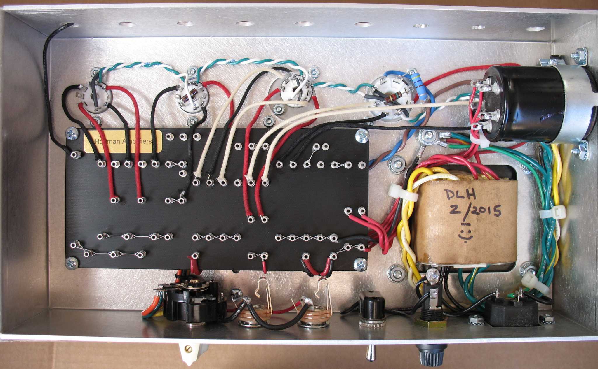
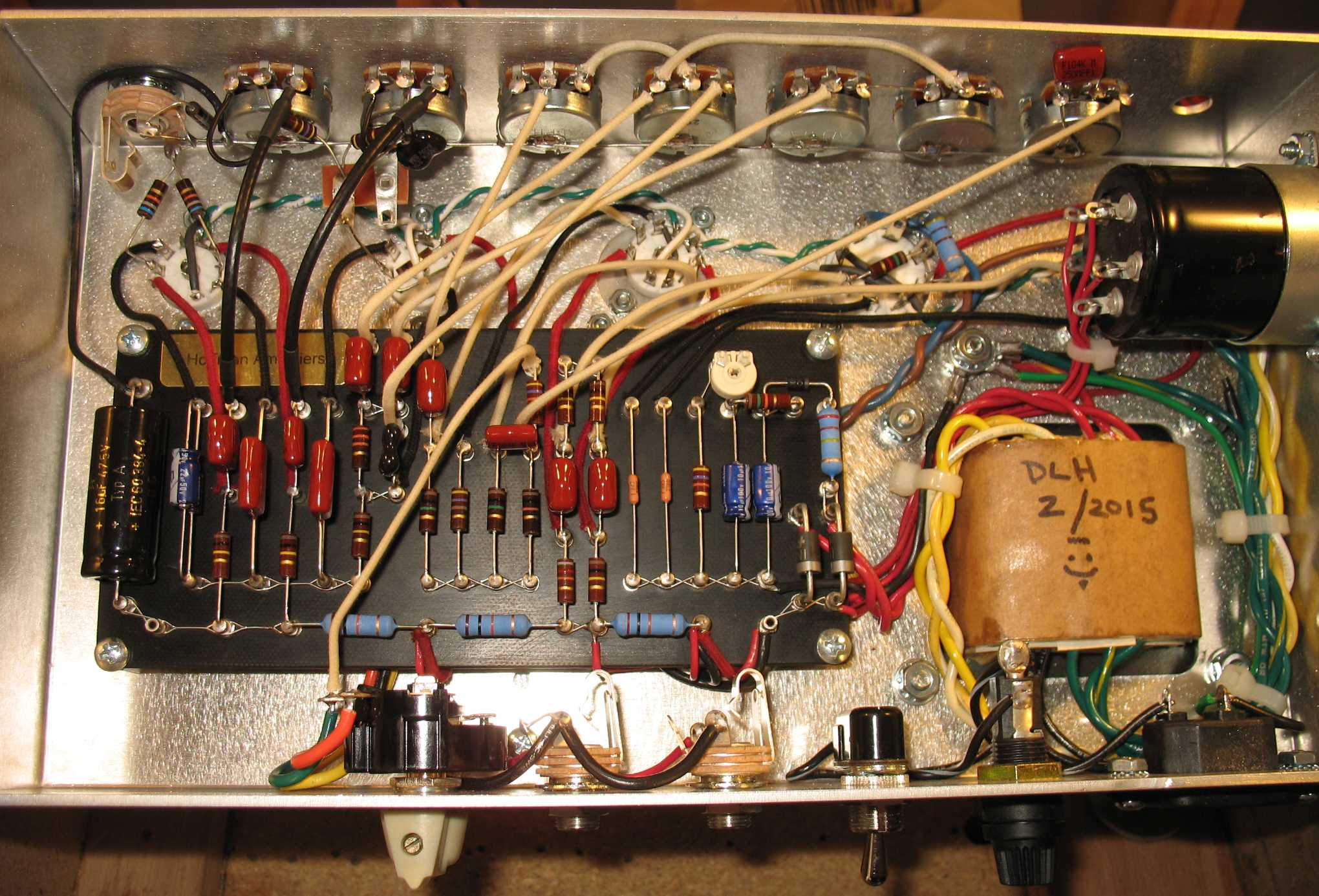
| The board has been mounted in the amp after all the infrastructure wires have been connected Notice the Chassis ground screw near the power transformer All the major grounds go to this point using soldered on #8 ring terminals The power transformer in this image has a filament center tap wire (green with yellow stripe) The red filter cap wires have been wired to the board in the image above The black ground wire at the right end of the board has been connected to chassis ground I like to use 18 gauge stranded PVC wire for the impedance selector, speaker jacks, power switch and fuse holder connections |
|
|
Detailed info on how to mount the Turret Board in the amp chassis: Place the circuit board inside the amplifier where it will be installed. Decide where you want to have your board mounting holes. Drill the mounting holes in the board. After the mounting holes have been drilled in the board, use a sharp object or a pencil to mark the location of the mounting holes on the chassis. Look under the chassis to make sure that you are not going to be drilling into an object such as a transformer. If the mounting holes happen to be where a transformer is, then you can either move the transformer or change the mounting hole locations on the board. It's a good idea to plan your circuit board mounting holes carefully before you start. It's easier if you are starting with a blank chassis. Make sure there are no screws sticking up under the board that are tall enough to touch anything on the bottom of the board. Remove the board and use a punch to mark where the mounting holes will be drilled in the chassis. Punches work better if you use a piece of wood on the backside of the chassis as a solid backing support. Drill the mounting holes in the chassis using a 3/16 inch drill bit for #8 sized screws. The bit should be just slightly larger than the mounting screws, so it will be easier to position the board. Mount the board into the chassis using #8 Screws, Keps Nuts and Standoffs. If you are also installing transformers, you may want to install them first if any screw heads are going to be under the board. It will be difficult to install a transformer later if the screw heads are under the board. I suggest having the transformer screw heads under the board and the nuts on the outside of the chassis. You do not want any screws coming up and shorting out things on the bottom of the board. Use some Loctite on the transformer mounting nuts so that they do not come loose. I remove the board at this point and do all the infrastructure wiring that I mentioned up above. |
|
| - | |
|
Lacing up and soldering the turret lugs: I do all the lug lacing and under the board wires after I have figured out where the board will be mounted and drilled all the board mounting holes in the chassis I like to install the boards with no components on the board and then add the components after the board has been wired up. It makes for a much cleaner installation and it's easy to clean off solder flux spots before you install the components. It's easy to mess up or bend installed component leads if the parts are already installed on the board and you try and wire it up. It's up to you on how you prefer to do the install. This page has a video on how I lace up and solder turret lugs |
|
| - | |
| Click on the image below to see a larger image | |
 |
|
|
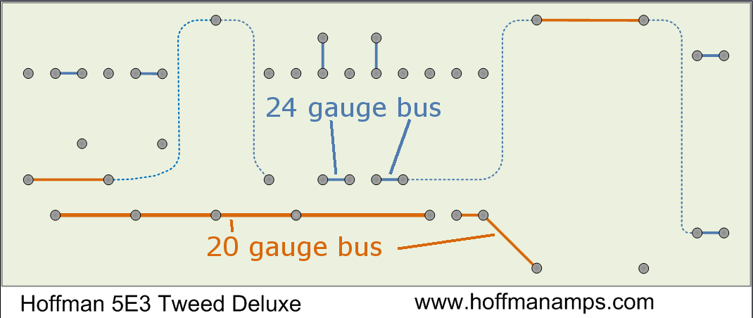
Lug lacing wire tip: I like to use 24 gauge bus wire for most of the shorter lug spans For longer lug spans, power rails and ground bus runs, I like use to 20 gauge bus wire For example: in the image above, the 24 gauge is the blue wire and the 20 gauge is the orange wire |
|
| - | |
| Click on the image below to see a larger image | |
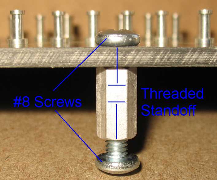
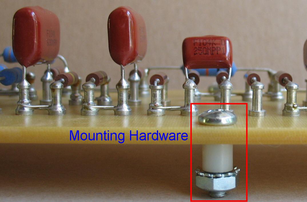 Board mounting method #1 The screws in the image above are #8 screws and are 5/8 inches long. They are the perfect length to go through 1/8th inch thick board material, through a 1/4 inch tall standoff, through the chassis and still have some threads showing I use #8 Keps nuts and #8 standoffs. Standoffs can be threaded or no threads, it's up to you. This method works well for boards that can be very close to the chassis surface. |
|
| - | |
 |
|
| Board mounting method #2 The other method I use is to raise the board up off the chassis a bit using taller standoffs I do this on some builds because there are transformer wires or tall screws coming into the chassis under the board and you need more space under the board Make sure your mounting screws are not too long If two screws meet and touch inside the standoff, you will not be able to tighten down the screws. In the picture above I used a 1/2 inch #8 threaded standoff I normally use #8 x 1/4 inch screws on the chassis side and #8 x 3/8 inch screws on the board side It does not matter as long as you make sure the screws are not too long You also need to make sure the screws are not too short so you have enough threads engaged on the screw |
|
| - | |
| Click on the image below to see a larger image | |
 |
|
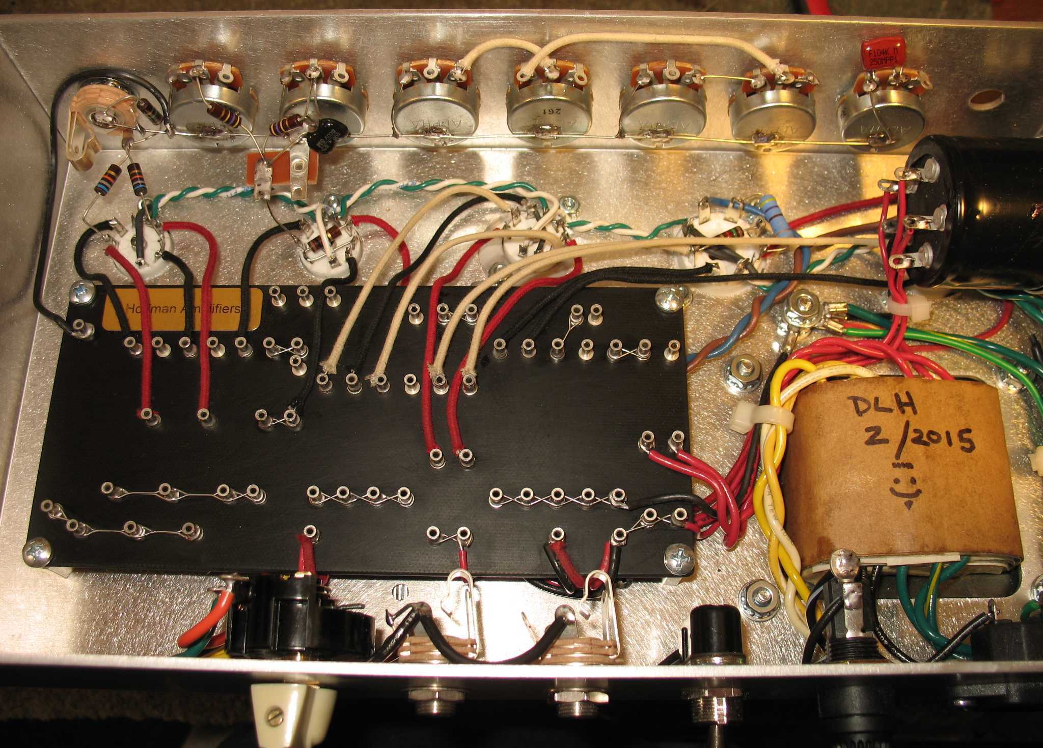
| All the tube socket wires have been wired except a couple of wires that come down from the pots and input jack Those wires will be added after the pots and input jacks have been mounted |
|
| - | |
| Detailed info on Wiring up the tube sockets: Make sure you insert tubes into the sockets before you start soldering wires to the sockets. You may not be able to get a tube into the socket if you wire them up without tubes in the sockets. Note that I have usually already installed the filament wires by this point. That depends on whether they lay down on the chassis or fly above the tube sockets. Face the front of the amp towards you just like the wiring diagram layout and start with the first pre-amp tube. On the pre-amp tubes you should do each pin in the sequence shown below. I wire up my 9 pin sockets like this: Pin3 - Pin2 - Pin1 - Pin6 - Pin7 - Pin8 The only exception is if a wire needs to fly overhead and it will be in the way, I will wait and do that wire later. Suggested wire colors: Use the wire colors shown in the diagram below when wiring the amp. I like to attach each wire to a turret lug first and then to the tube socket pin last. Starting with Pin 3 of the first pre-amp tube, strip enough of the black hook up wire so that it can wrap around the base of the turret lug. If you make a half loop around a piece of tubing or something roughly the same size as the lug it is easier to form the wire around the base of the lug. Solder the wire to the turret lug with enough heat to solder the wire correctly. Then lay the wire out and run it up to the pin on the tube socket. The wires should not be over the top of the tube socket. They should go around the socket on their way to the pin they will be connected to. Cut the wires to the correct length. The wires should not be too long or too short. They should be as short as possible with just a little curve for flexibility. Strip the wire and solder it to the correct tube socket pin. Check the lay out diagram often to see if you are connecting everything correctly. You may want to keep the red wires, going to Pin 1 and 6, away from the black and white wires. You can suspend the red wires above the other wires or the other way around but they should not be laid next to or parallel to the black and white wires. The red plate wires contain the high voltage and may induce noise into the other low voltage wires. Continue Connecting all the wires to the tube sockets Once all the board wiring has been done you can clean the board of any flux spray before you install the components This will make your build look really nice |
|
| - | |
 |
|
| Suggested colors for hookup wires Black = Cathodes or grounds White = Signal wires Red = Plates and high voltage Green = Filaments I like to use 22 gauge cloth push back wire or 20 gauge PVC hookup wire for all the board connections. You do not need to strip cloth wire, just push back the cloth a bit to expose the wire |
|
| - | |
| Click on the image below to see a larger image | |
 |
|
| The pots and input jack have been installed and a buss wire has been soldered down the back of the pots Parts and jumper wires have been installed on the pots |
|
| - | |
| Detailed info on Installing the pots and input jacks: Install the pots into the front panel. Install the jacks into the front panel. Solder a bus wire down the back of the pots. 20 gauge bare wire is fine for the bus wire. You can strip the insulation off of jacketed solid core wire to make a bare bus wire If the pots have a coating on the metal, the solder will not stick. I use a Dremel tool to grind a clean spot on the pot and I solder to that spot. You can use a bit of sandpaper to scuff up the pot surface Connect the ground on the jacks to the bus wire. Connect the black ground wire from the left preamp end of the circuit board to the ground bus that runs along the backs of the pots. Install the resistors on the input jacks. Shielded RG174 cable should be used to connect the input jacks to the pre-amp tubes. Cut the cable to the correct length by routing it directly from the jacks to the tube socket. Leave just a little slack in the RG174 shielded cable. Connect the shield of the cable to the ground bus on one of the jacks. Strip the tube socket end and remove the outer shield. You will only connect the center wire to the tube socket pin. Use some heat shrink to cover the outer shield on the tube socket end so it does not touch anything and cause problems. Shrink the heat shrink with the barrel of your soldering iron or use a heat gun See the images further down the page on how I run my RG174 cable Note that the chassis in the image above does not need shielded cable because the input jack is right above the tube socket. The 68K input jack resistors reach down to the tube socket so there is no need for shielded cable |
|
| - | |
| Click on the image below to see a larger image | |
 |
|
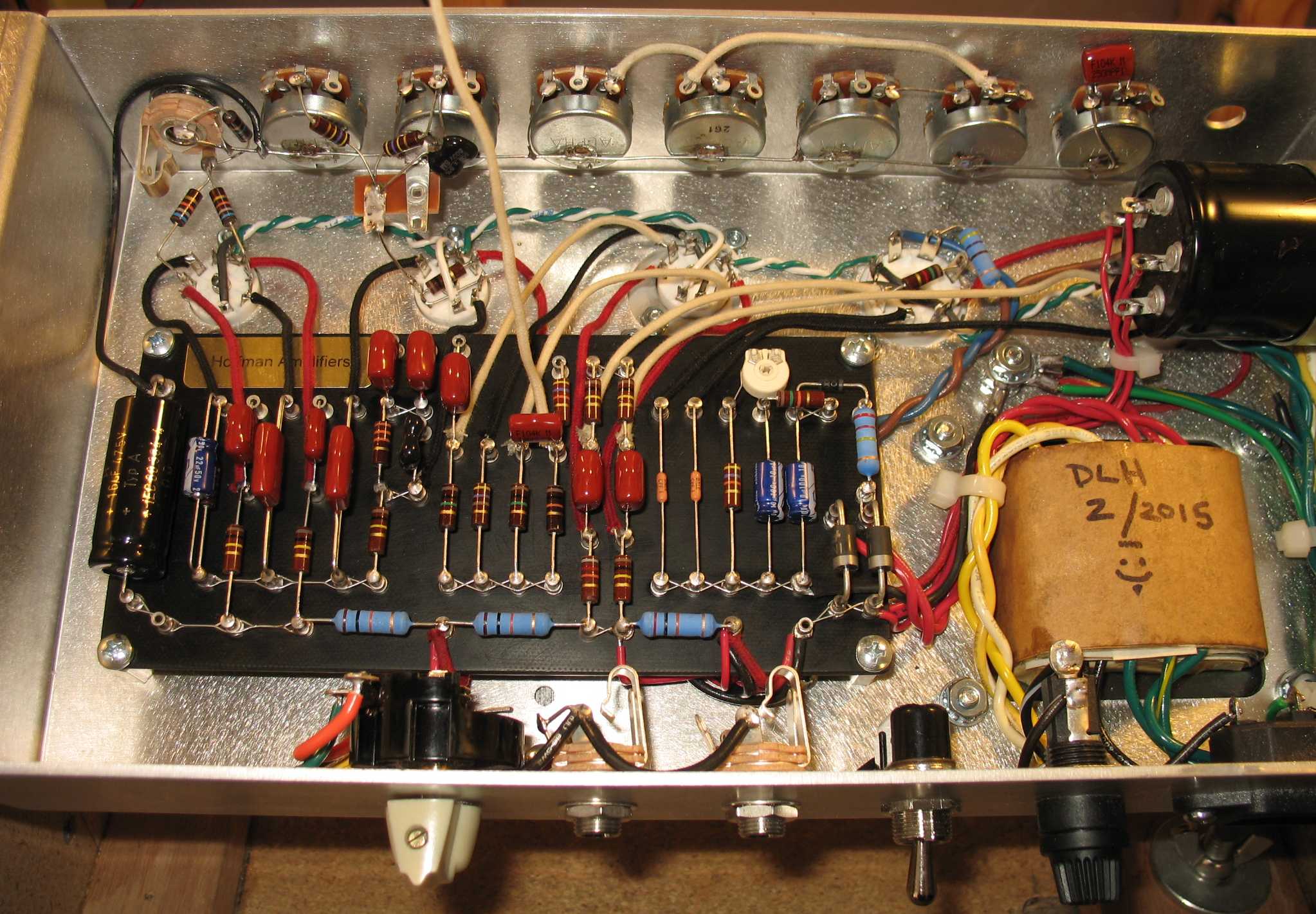
| Add the parts to the board Look how nice and neat everything because you waited to install the parts at this point in the build No bent component wires, no flux blobs all over the board |
|
| - | |
| Install the parts on the board: Here's where you should take your time and do a really nice neat job. Bend all your component leads nicely and insert them down into the turret lug holes Add a tiny solder domes to the tops of all the lugs that do not receive wires from the pots. You will wire up the pot wires last and so you do not want to close off the turret lug hole now. Look at your layout diagram as you go so you only solder the parts that need to get soldered now If you have two or more component wires in a lug hole and things are a bit tight, you can take a very sharp pointy tool and poke it down into the lug hole to expand it a bit. Rotate the sharp pointy tool a bit in order to make more room for other components leads |
|
| - | |
| Click on the image below to see a larger image | |
 |
|
| The pot wires have been installed The feedback wire is the white wire that goes from the rotary impedance selector switch to the board |
|
| - | |
| Connecting the pot wires: Connect each pot wire from the pot to the board using white wire. Strip one end of the white hook up wire and solder it to the pot tab and then find the location on the board where the wire will be attached. Cut the wire as short as possible leaving just a little play in the wire. Strip the end of the wire and insert it into the hole in the top of the lug. The wire will be in the same hole with a component. Solder the top of the lug carefully using just enough heat making a small solder dome A thin sharp soldering iron tip is a big help when doing fine soldering like this. TIP: You can expand the lug hole by inserting a tiny pointy tool into the hole. Hook up the feedback wire if you have one. Solder a white wire to one end of the Feedback Resistor lug and solder the other end to the speaker tap you are going to use. Some wires leaving the pots may be RG174 shielded cable, look at your layout diagram. The cable shield must be grounded at the pot end of the wire. The other end just has the center conductor sticking out. |
|
| - | |
 |
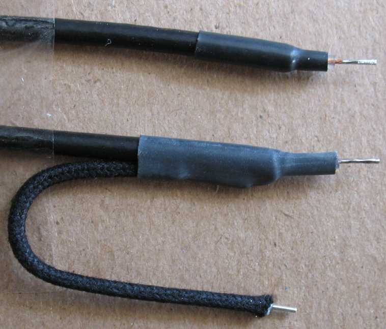 |
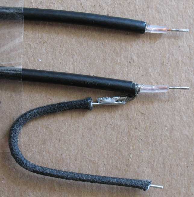
| This is how I run my RG174 shielded cables Top: Strip one end and remove all the braided shielding and then tin the center conductor with solder This is the end that goes to the board or to a tube socket pin Bottom: Strip the other end and bundle up the shield by twisting it Tin the shield with solder and tin the center conductor Do not apply too much heat to the braid or it will travel back and melt the center conductor jacket This will result in a shorted center conductor wire Solder on a ground wire that you will connect to a ground source This is the end that goes to a pot or an input jack Slip on some .125 inch diameter heat shrink tubing and shrink it |
|
| - | |
| Double check all your work: Stop now and look at this post on my forum on how to double check all your work, this is very important How to double check your work the easy way Do not continue until you have double checked everything using my method above Every time someone has an issue with the amp not working it is always because they skipped a step or did not double check their work thoroughly. Hoffman law says this. The amp would be working if it was wired properly and all the parts were installed and working correctly |
|
| - | |
| Powering up the amp and setting the bias After all connections have been made and double checked Power up the amp with no tubes in the sockets. Using a multi-meter set on DC volts Check to see if pins 1 and 6 on the pre-amp tubes have high voltage 9 pin tubes have different configurations. Look at the schematic to see which pins should be measured. Check pins 3 and 4 on 8 pin power tubes to see if they have high voltage. Check Pins 7 and 9 on EL84 power tubes to see if they have high voltage. Go to the Cathode biased section or the fixed bias section below Depending on the amp you are building |
|
| - | |
Read this for Cathode biased amps: If your board is cathode biased, you will not be setting the bias of the amp with a bias pot. Examples of cathode biased amps are 5E3 and AC30. You can alter the bias by changing the power tube cathode bias resistor. Insert all tubes into their sockets and turn on the amp, you are done. You can make a voltage chart of all the tubes for your records and for trouble shooting purposes. Turn on the amp and check the voltage reading across your shared power tube cathode resistor to see if it is where it should be. You can adjust the cathode resistor value up or down to bias the power tubes A higher value resistor results in a larger voltage drop across the resistor and less bias current flowing through the power tubes A lower value resistor results in less of a voltage drop across the resistor and more bias current flowing through the power tubes There is only so much you can do on a cathode biased amp to adjust the bias by adjusting the shared cathode resistor The high voltage going to the plates of the power tubes is usually power in a cathode biased amp than it is in a fixed bias amps If your power tubes are running excessive current and the cathode resistor is set correctly, you may need a power transformer that produces lower plate voltages If all your voltages look good and your bias current is ok, you can make a voltage chart of all the tubes for your records and for trouble shooting purposes. Play your amp and enjoy it. Skip past the fixed bias section below. |
|
| - | |
|
Read this for Fixed bias amps: Check pins 5 on the 8 pin power tubes to see if they have negative bias voltage. This pin 2 on fixed bias EL84 power tubes Turn the bias pot so that pin 5 (pin 2 on EL84 amps) has the most negative voltage that the bias circuit can produce. This is done so that the power tubes will be over biased when you first turn on the amp with the tubes inserted. You do not want to turn on the amp and have the power tubes go into maximum current draw and possibly damage them You should have enough negative bias voltage so that you shut down the power tubes by over biasing them If not completely turning them off, then you should be able to throttle the power down way down to almost not current flowing in them. Continue on here to bias fixed bias amps after you have turned the bias pot so that you have maximum negative voltage going to the power tube socket pins Insert all tubes into their sockets. Connect your multi meter across one of the 1 ohm power tube cathode resistors if your board has them Set your multi meter to DC Millivolts On the one ohm resistors, positive goes to the power tubes, negative goes to ground. Set your meter on DC Millivolts. Current flowing through a one ohm resistor results in a voltage drop across the resistor So you are reading a voltage drop in DC Millivolts, but you are measuring DC Milliamps current flowing through the one ohm resistor You are going to watch the power tube current flowing on your multi meter as you turn on the power switch or the standby switch. If you have a standby switch: Power up the amp and let it warm up for 30 seconds with the standby switch off. Turn on the standby switch if the amp has one and watch the meter. Be prepared to quickly turn the standby switch off if the current is too high on the power tubes. If you do not have a standby switch: Turn on the amp and watch the meter. Be ready to turn it back off quickly If the current rises way above the target bias current, turn the amp off and make sure you have set the bias pot to the most negative voltage that it will go Go back up and read this section again from the beginning If the current reading is very low, then you can bias the amp to where ever you are going to bias it. A generic current setting for 6L6 and EL34 fixed bias amps is around 35 milliamps per tube EL84's and 6V6's will be much lower. Maybe around 25 milliamps per tube for a generic setting Note that these are just generic settings to get you going. If the current rises above the generic targets mentioned above, and your bias pot is turned all the way the most negative it will go, you may not have enough negative bias voltage and the bias range resistor in the bias circuit may have to be lowered in value. see the section below on adjusting the bias range resistor If all your voltages look good and your bias current is ok, you can make a voltage chart of all the tubes for your records and for trouble shooting purposes. Play your amp and enjoy it |
|
| - | |
Adjusting the bias range resistor on fixed bias amps: Turning the bias pot from one end to the other is your negative bias voltage range You can measure this on the power tubes and see what this range is Pin 5 on 8 pin power tubes and pin 2 on EL84 power tubes is the point you can measure this negative voltage. If your bias range needs adjusting, you may have to adjust the bias range resistor on the board in the bias circuit Your bias range resistor may need adjusting if you cannot get a good bias current range on your power tubes You can raise or lower the value of the bias range resistor to get a correct bias range sweep in your bias pot. A higher value bias range resistor will result in less negative voltage in the bias circuit A lower value bias range resistor will result in more negative voltage in the bias circuit Example 1: You turn the bias pot all the way to the most negative voltage setting and your power tube current is higher than the target current reading. You need more negative voltage in your bias circuit. Lower the value of the bias range resistor Example 2: You turn the bias pot all the way to the least negative voltage and your power tubes current is lower than the target current reading. You need less negative voltage in your bias circuit. Raise the value of the bias range resistor |
|
| - | |
Filament notes: Pins 4 and 5 get jumpered together on 9 pin pre-amp tubes and go to one side of the 6.3 volt ac filament wires coming from the power transformer. Pin 9 is the other side if the 6.3 vac filament wire coming from the power transfromer. If you are building from scratch you will have to run your filament wires in a parallel twisted pair manner to each tube socket. If you are using an existing chassis, the filament wires may already be in place. I like to use green 18 gauge stranded wire for the power tubes and green 20 gauge solid core wire for the pre-amp tubes. You can the filament wires flush to the chassis surface like in a vintage Marshall or overhead like in vintage Fender amps The overhead Fender method: Run the twisted pair of filament wires about an inch over the top of the tube sockets and come straight down to the pins. Flush on the chassis surface method: Run your twisted pair off to one side of the tube sockets. Branch the wires off and loop around the socket to reach the pins Both filament wiring methods: Keep the pins numbers the same from socket to socket. For example, pin 9 on the first pre-amp tube would go to pin 9 of the next pre-amp tube and so on down the line to all the 9 pin tube sockets. The power tube filament pins are 2 and 7 on 8 pin type power tubes. Pin 2 of the first power tube goes to pin 2 of the next one and the same with pin 7. EL84 power tubes use pins 4 and 5 for the filament connections. Pin 4 of the first power tube goes to pin 4 of the next one and the same with pin 5. This keeps the ac filaments in phase with each other. You make get a hum in the amp if you run the heater wires out of phase, so keep the same wire going to the same pins Soldering tips: If the solder on the top of the turret lug gets sucked down into the lug, wait until the lug has cooled down and then return to the lug to add a little bit of solder where the components leads are inserted. Never keep adding solder to a hot lug that keeps sucking it in. First, you are probably heating up the component too much and secondly the lug may be dripping solder out the bottom. This may lead to a solder blob that could touch the metal chassis and short out the board. Solder all the wires to the tube sockets and then come back and re-solder the tops of the lugs all at once after everything has cooled down. Final Notes: Take your time installing the boards. Do not rush Do not skip steps. Double check everything again and again. This page on my amp forum has important info on how to double check all your work Go to my amp forum here if you need tech help, but do the double check step first in the line up above this one |
|
Click on the image to see a larger image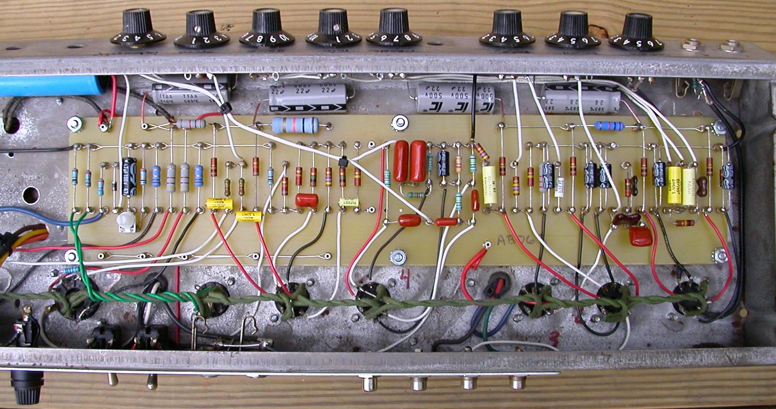
|
|
| Here's an example of a Hoffman Turret board installed in an old junked out Fender chassis Notice how I run my filter caps and avoid having to use a cap board and cap can. |
|
| - | |
Click on the image to see a larger image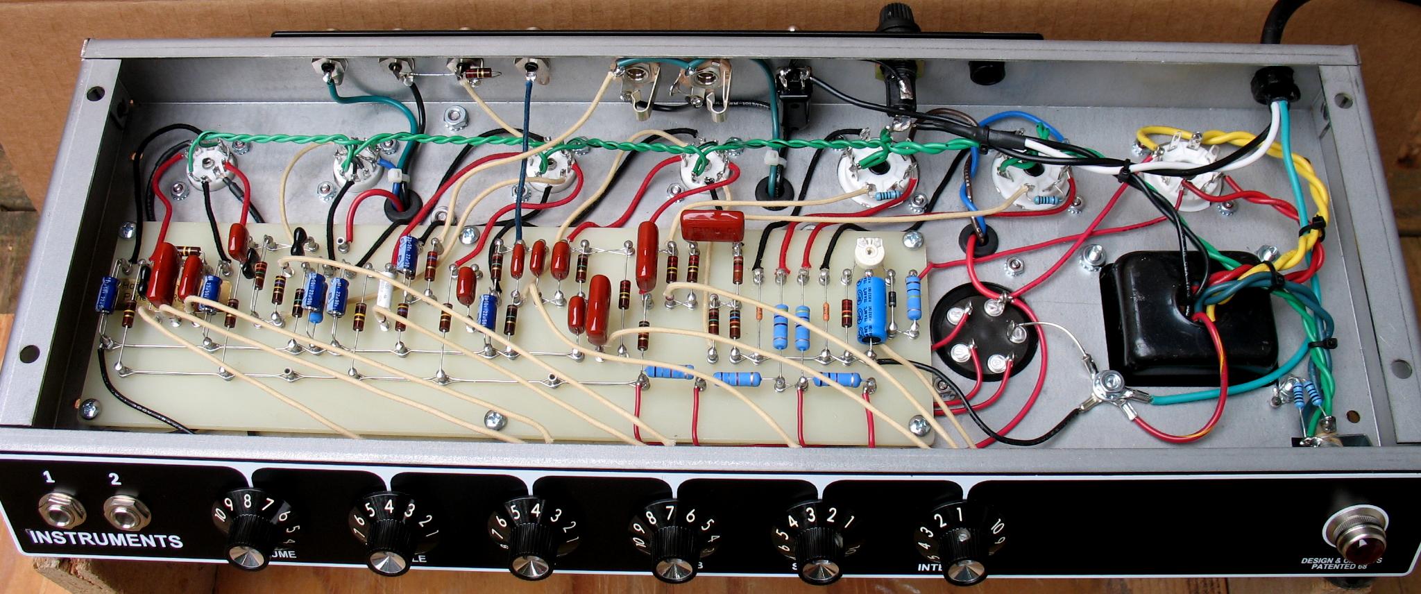
|
|
| This is a Princeton Reverb with a Hoffman Turret Board | |
| - | |
| Go to my library page here to see many more builds I have done It always helps to see pictures of other builds |
|
| - | |
Enter My Tube Amp Parts Store Here
Mobile users Enter My Tube Amp Parts Store Here
The Tube amp Library of information
Click the link above for Tube amp info, Schematics, Board building information, Projects, Mods, Transformer diagrams, Photo's, Sound clips.
There are hundreds of pages of Tube amp information on my library page.
Please visit my Tube Amplifier Forum
Here's the place you can go to ask tube amplifier questions.
You will find a large community of friendly amp builders at the link above.
Check the huge library of Schematics here
Design your own custom Turret Board or Eyelet board
DIY Layout Creator file analyzer program
DIY Layout Creator file library
How to email me
|
MEMBER OF PROJECT HONEY POT Spam Harvester Protection Network provided by Unspam |