
| Back to Library page |
Tube Amplifier Chassis Grounding info |
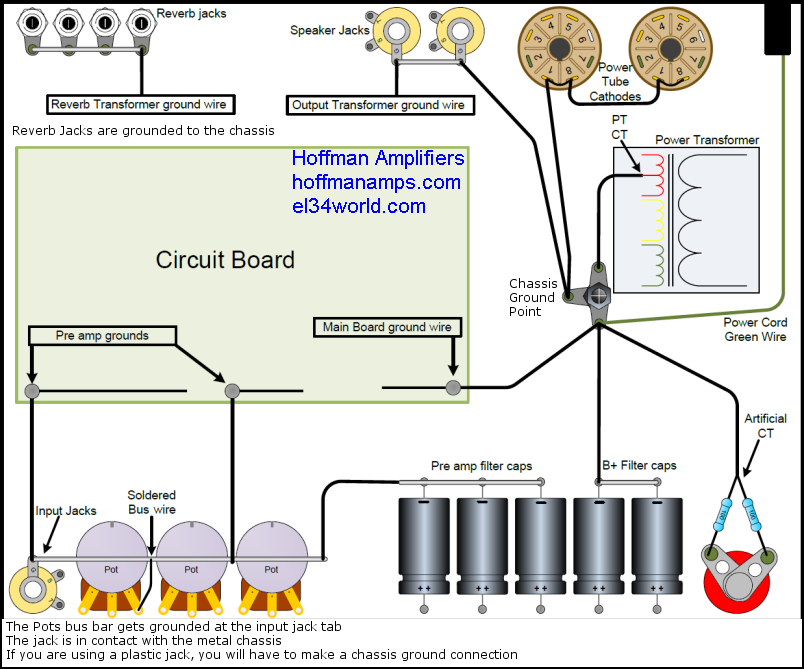 |
| Click the image above to see a larger image The diagram above shows the grounding scheme that you find on most Vintage Fender's and Marshall's. The grounding scheme above runs very quiet if done properly. |
| Do not try and solder wires to the chassis itself.
A ground that is soldered to a chassis is not as good as a soldered and bolted down ring terminal ground Plus it takes a very large soldering iron to be able to solder to a chassis Do not do STAR grounding. I have removed many star grounds in amps to fix grounding problems. Do not use the brass Fender style grounding plates. These plates corrode eventually and do not make good contact between the chassis and the brass. Drill a hole near your power transformer and bolt down the grounds as shown in my image above Crimp and solder ring terminals to the wires. Ring terminals make it easy to bolt grounds down the the chassis The Marshall style pot bus wire is shown above. This is a bare wire that is soldered to the back of every pot and is connected to the input jacks ground lugs. I recommend using this bus wire system. You may have to grind, sand or file some of the coating off of the back of the pots so that you can solder the bus wire to it. A 40 watt iron minimum is usually what it takes to solder this bus wire to the pots. Make sure all Jacks and pots are bolted down firmly to the metal chassis. The bus wire makes it's chassis ground through the input jacks If you use plastic jacks, make sure all jacks are grounded to the pot bus wire. You will have to make a chassis ground point if you use plastic jacks Your circuit board may have multiple grounds leaving the circuit board. Pre amp grounds are soldered to the pot bus wire. Bias supplies, rectifiers or power tube cathode ground wires all go to the main ground point. All power transformer Center taps get bolted down to the main ground point If you use two 100 ohm resistors as your heater center tap, do not use the power transformer heater center tap wire and visa versa. If you have a reverb transformer, make sure the reverb jacks are bolted to the chassis and the reverb transformer ground wire is soldered to a ground lug on the reverb jacks. Do not use insulating washers on the reverb jacks. Speakers jacks are bolted firmly to the metal chassis. The output transformer ground wire is soldered to a speaker jack ground lug. If you use plastic speakers jacks, solder a ground wire to the jacks and bolt it down to the main ground point Your power tube cathode wires may be on the circuit board or leave the tube sockets and go right to the main ground point The power cord green wire can be bolted down to the main ground point If you have a separate rectifier board or a bias circuit board or a Bridge rectifier bolted down somewhere, all these grounds should get bolted down to the main ground point |
Enter My Tube Amp Parts Store Here
Mobile users Enter My Tube Amp Parts Store Here
The Tube amp Library of information
Click the link above for Tube amp info, Schematics, Board building information, Projects, Mods, Transformer diagrams, Photo's, Sound clips.
There are hundreds of pages of Tube amp information on my library page.
Please visit my Tube Amplifier Forum
Here's the place you can go to ask tube amplifier questions.
You will find a large community of friendly amp builders at the link above.
Check the huge library of Schematics here
Design your own custom Turret Board or Eyelet board
DIY Layout Creator file analyzer program
DIY Layout Creator file library
How to email me
|
MEMBER OF PROJECT HONEY POT Spam Harvester Protection Network provided by Unspam |