
| Back to Library page |
| - |
My Rack ReVibe
ReVibe info pages |
| - |
| Click on the images to see larger images |
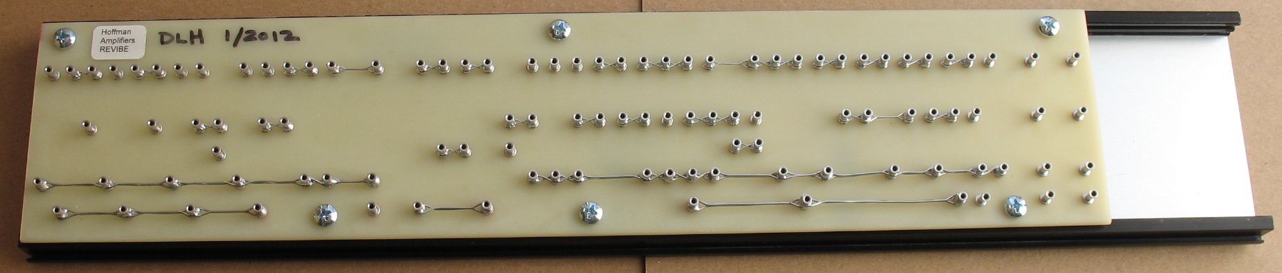 |
| This is one of my pre-drilled ReVibe boards with all the lugs installed The lugs have been laced together. The board has been mounted to the bottom of the rack floor with 1/4" standoffs, 5/8" # 8 screws and #8 keps nuts |
| - |
| Click on the images to see larger images |
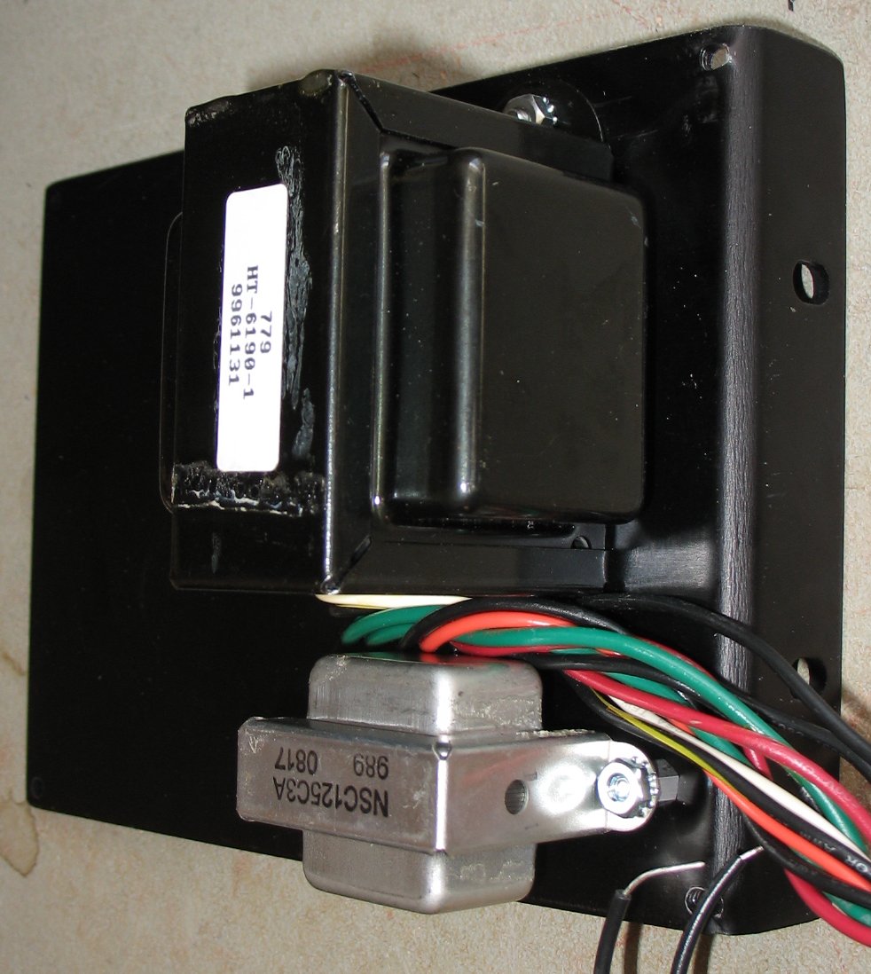 |
| I mounted the power transformer and choke on the right side rack piece |
| - |
| Click on the images to see larger images |
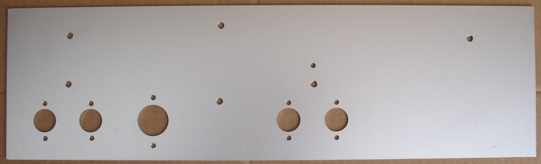 |
| This is the back panel after if was cut on my CNC machine |
| - |
| Click on the images to see larger images |
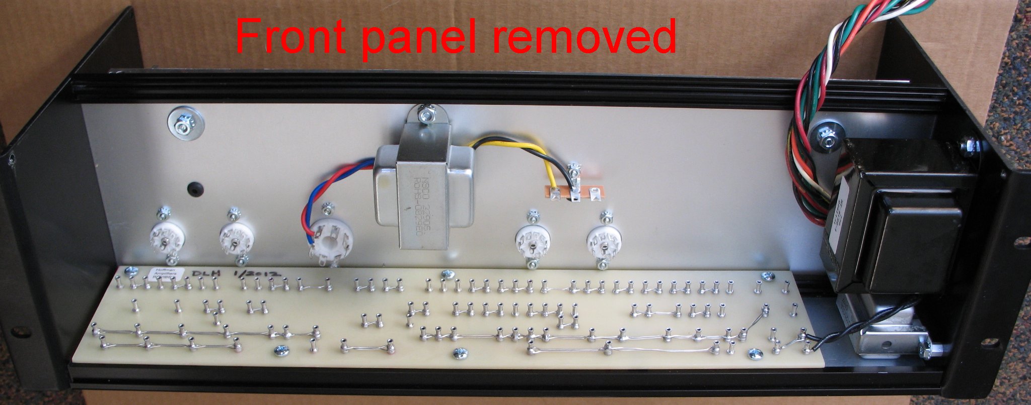 |
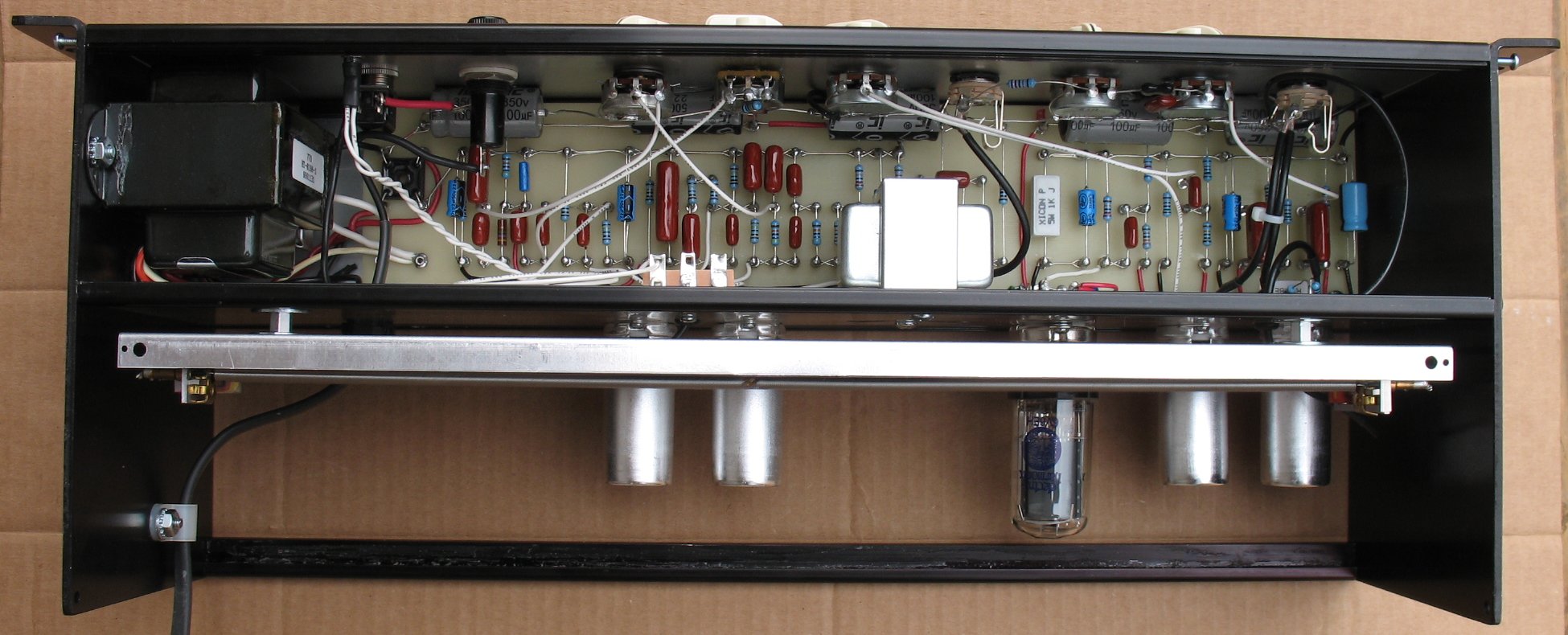
| The back panel has been attached to the rack sides The tube sockets are bolted in using #4 screws and nuts The output transformer is bolted in place between the 6V6 and the first vibrato section tube Now you can see how the power transformer and choke sit right next to the board |
| - |
| Click on the images to see larger images |
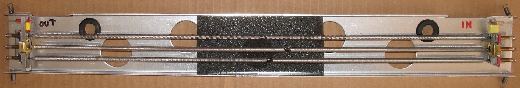 |
| I removed the center spring assembly from a 9AB3C1B 3 spring reverb tank |
| - |
| Click on the images to see larger images |
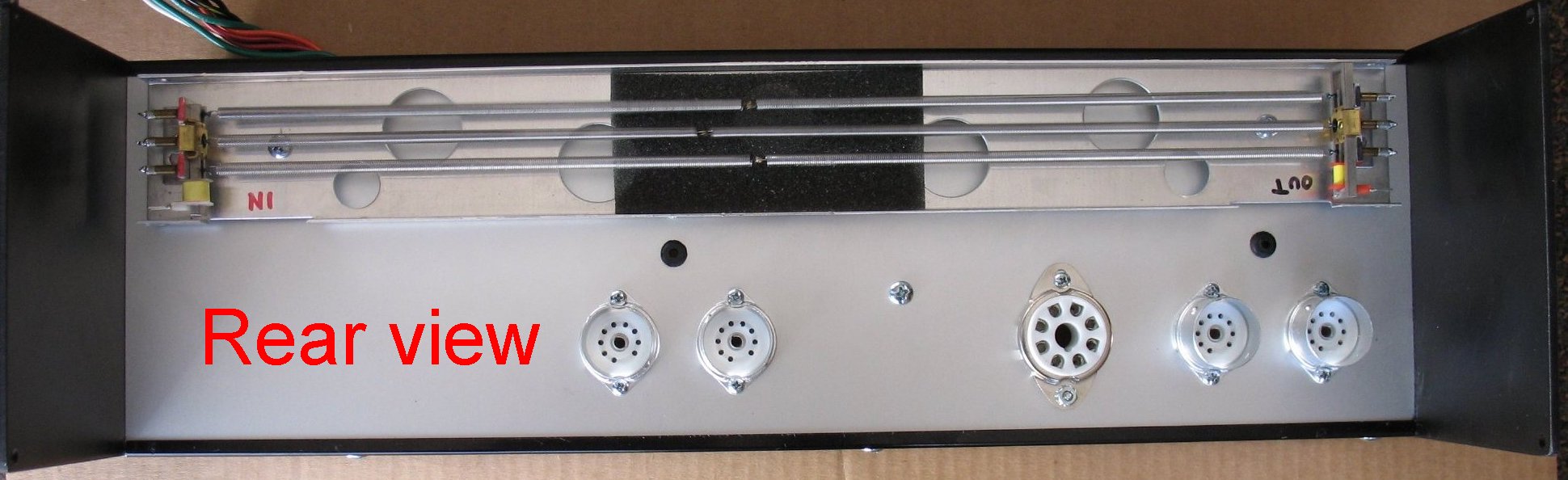 |
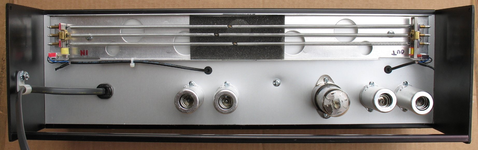
| This is the rear view of the back wall The reverb springs sit right above the tubes The output end of the tank needs to be as far from the power transformer as is possible to avoid hum. The input end is less critical because the signal level is much higher than the output end |
| - |
| Click on the images to see larger images |
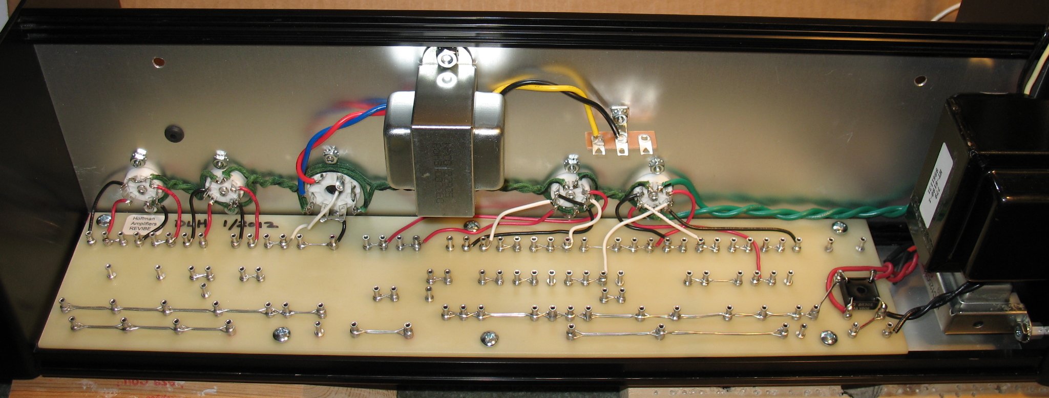 |
| The tube sockets have been wired up The heater string has been wired up |
| - |
| Click on the images to see larger images |
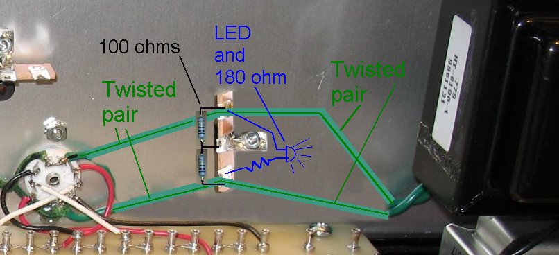 |
| Note that I would run the heater string differently next time. I would insert a 3 lug terminal strip right after the power transformer The green heater wires from the power transformer would go to the terminal strip From the terminal strip you will have 2 sets of wires leaving One twisted pair goes on to the tube sockets One twisted pair goes to the LED pilot light On the terminal strip you can mount the two 100 ohm resistors to make the artificial center tap The foot of the 3 lug terminal strip is bolted to the chassis and makes the ground for the 2 x 100 ohm resistors. I forgot all about these other items and had to wedge in these parts later on |
| - |
| Click on the images to see larger images |
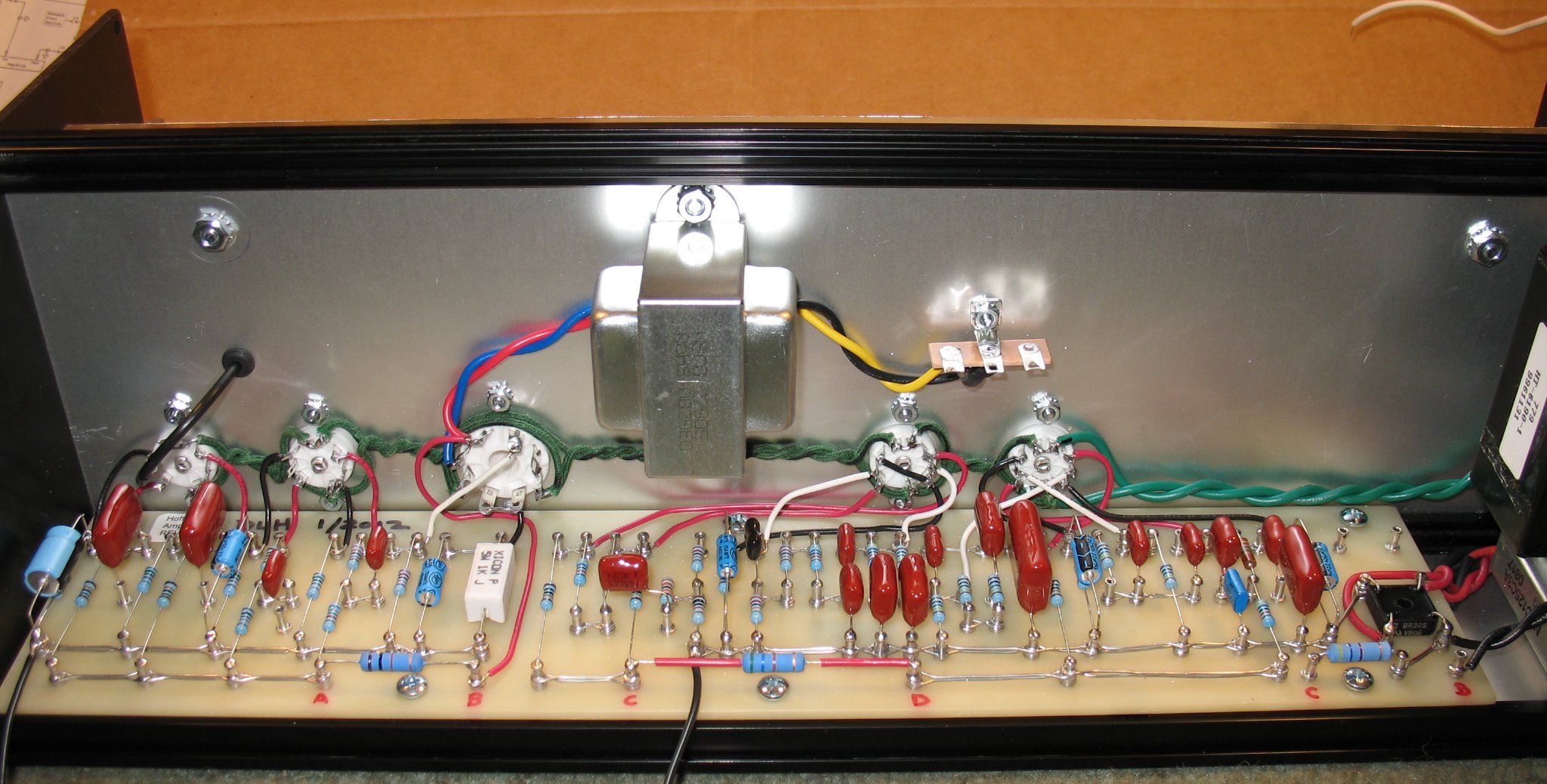 |
| The parts have been installed on the board Note that I do not put and solder on the lugs where pot wires are to be inserted later |
| - |
| Click on the images to see larger images |
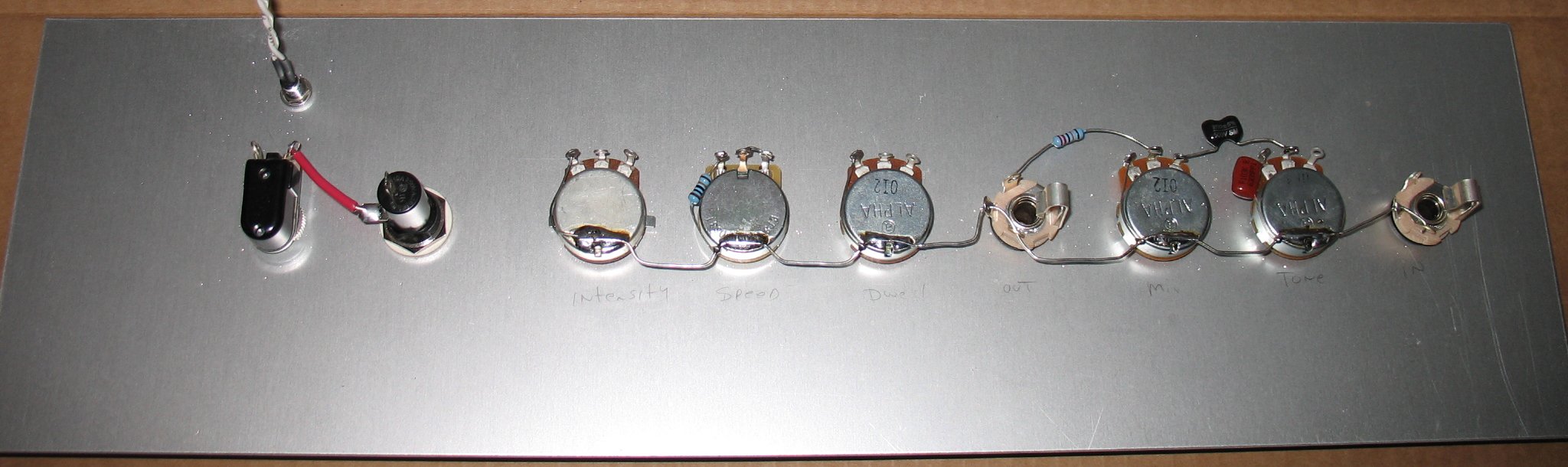 |
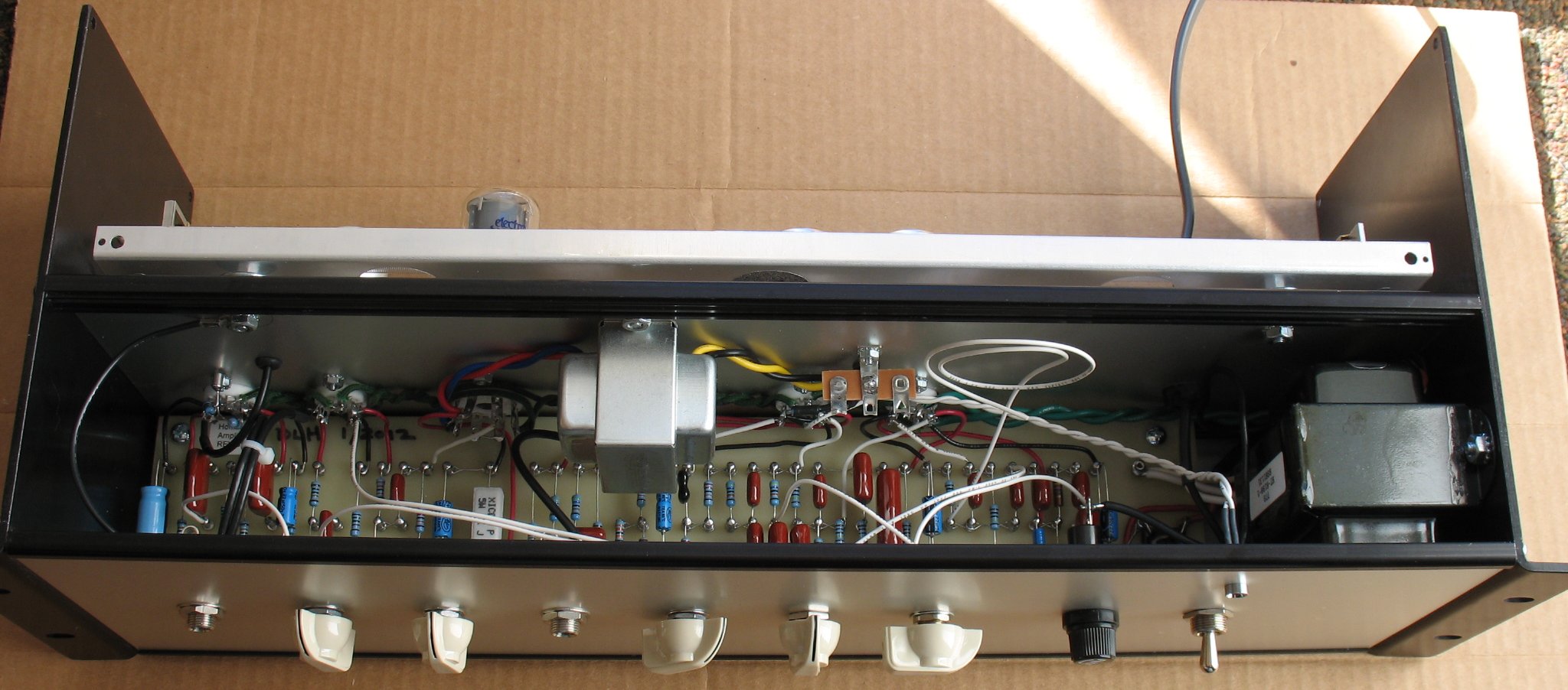
| The rear of the front panel The pots have a soldered buss wire running down the back Note that the speed control is wired wrong in this image I also forgot to add the 1 meg resistor on the input jack The layout diagram shows the correct wiring for the pot string |
| - |
| Click on the images to see larger images |
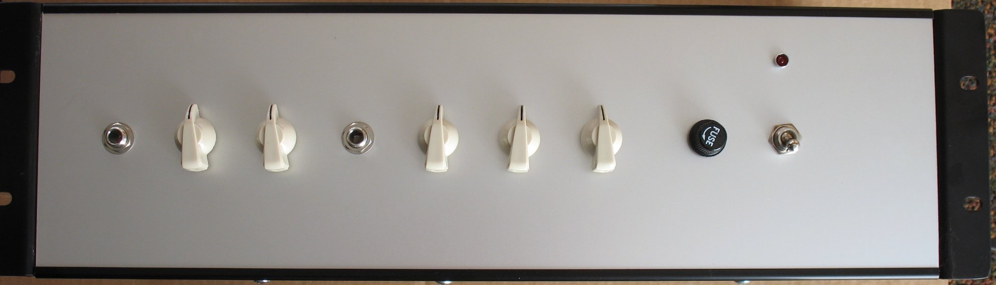 |
| The front panel |
| - |
| Click on the images to see larger images |
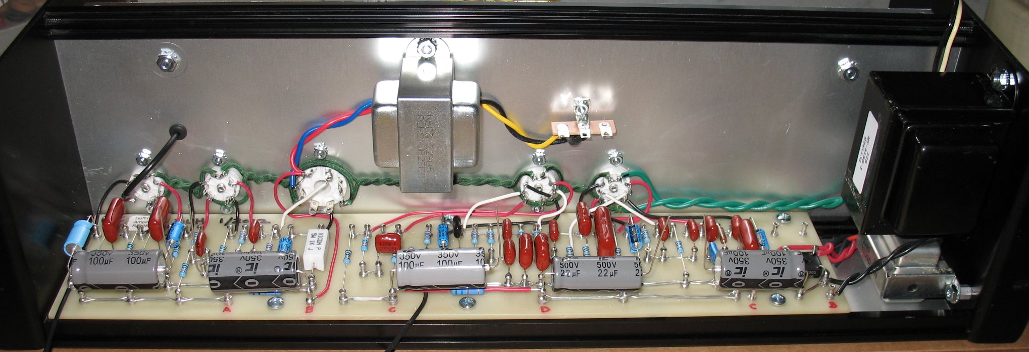 |
| The filter caps have been soldered the correct lugs the negatives of each cap go to the buss wire on the back of the pots When the front panel goes on, I add a bit of clear silicone to the sides of the caps to secure them to the front panel |
| - |
| Click on the images to see larger images |
 |
| The back panel with tubes, power cord and reverb cables A note on the power cord. I am only using the Hot and neutral wires The green ground is not being used to prevent a ground loop The guitar cord makes the ground connection back to your amplifier |
| - |
| Click on the images to see larger images |
 |
| Top view |
| - |
| Click on the images to see larger images |
 |
| Another top view |
| - |
| Click on the images to see larger images |
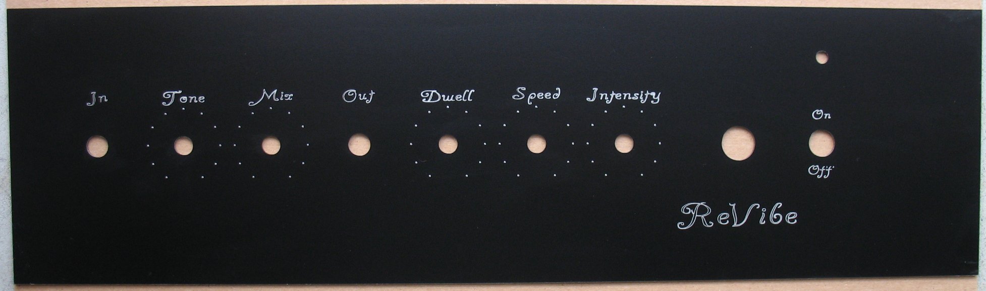 |
| The face plate I made on my CNC machine Please don't ask me to make face panels They are a royal PITA to make Sign shops have the right machines to make face panels |
| - |
| Click on the images to see larger images |
 |
| The face panel is rear engraved and then white paint is smeared on The material is a clear and black sandwich You engrave through the black just a tiny bit into the clear The front clear side is smooth to the touch |
| - |
| Click on the images to see larger images |
 |
| And here's the ReVibe with the face panel glued on |
| - |
| Click on the images to see larger images |
 |
| The top lid has been installed |
| - |
| Click on the images to see larger images |
 |
| Here's the ReVibe sitting in my rack From top to bottom: Palmer speaker emulator/Load box ReVibe My Stereo guitar tube pre amp My Stereo EL84 power amp |
| - |
Enter My Tube Amp Parts Store Here
Mobile users Enter My Tube Amp Parts Store Here
The Tube amp Library of information
Click the link above for Tube amp info, Schematics, Board building information, Projects, Mods, Transformer diagrams, Photo's, Sound clips.
There are hundreds of pages of Tube amp information on my library page.
Please visit my Tube Amplifier Forum
Here's the place you can go to ask tube amplifier questions.
You will find a large community of friendly amp builders at the link above.
Check the huge library of Schematics here
Design your own custom Turret Board or Eyelet board
DIY Layout Creator file analyzer program
DIY Layout Creator file library
How to email me
|
MEMBER OF PROJECT HONEY POT Spam Harvester Protection Network provided by Unspam |