
How to assemble the Hoffman Amps bias current checkersNote that Mojo Musical supply also sells my bias checkerUse these instructions to assemble the Mojo version also |
|
| - | |
| Click on the images below for a larger image | |
|
 |
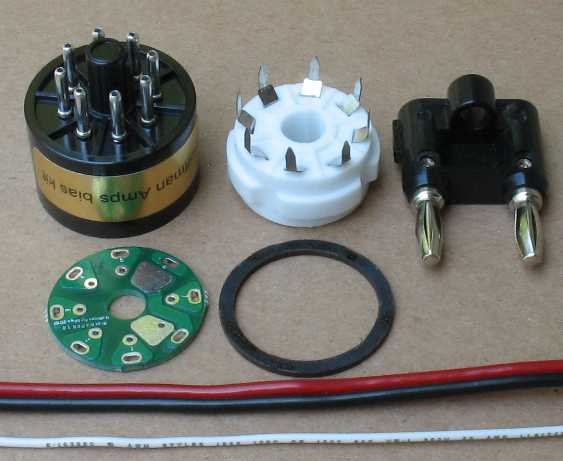
| The Bias Checker Parts | The tube bases with the wire hole already drilled and a gold sticker |
| Materials list for each Bias Current Checker 1 - 8 pin tube base with hole 1 - 8 pin PC board tube socket 1 - Dual banana plug 1 - Bias checker PCB 1 - Bias checker Ring 2 feet of 20 gauge zip cord 2 feet of 20 gauge bus wire The bias checker can be ordered as a kit on this page in my parts catalog |
|
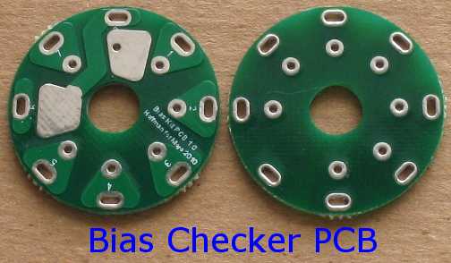 The bias checker boards come to me on sheets and are connected together by small tabs I break the sheets apart but some of the tabs are still attached to the board You can snip off the tabs or sand them off The board should be perfectly round before you begin assembly The board should be able to drop right down into the tube base Note that Mojo makes these for me and they have update them. So the images may not look exactly like current models. See the two images below Click on the image below to see a larger image 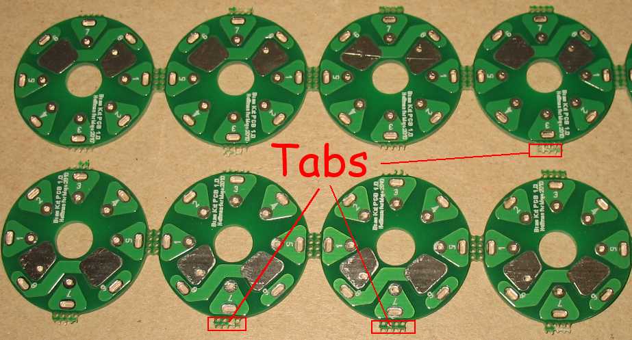 Trim these tabs off The board should drop into the base without forcing it 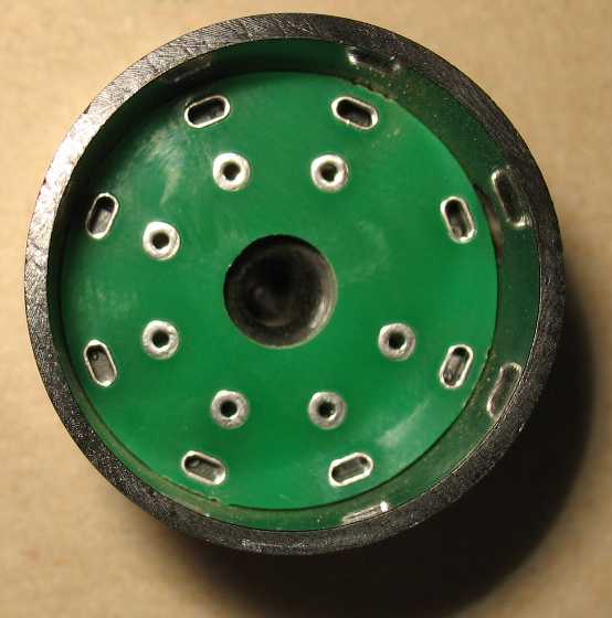 |
|
 |
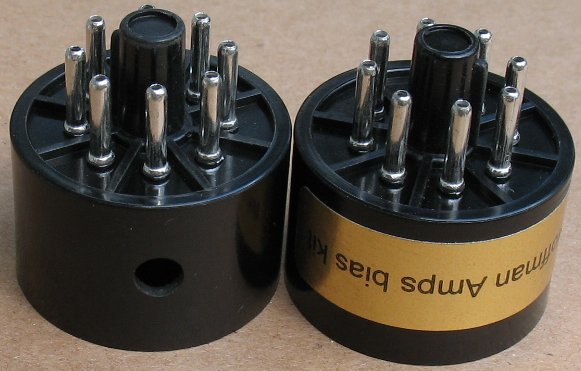
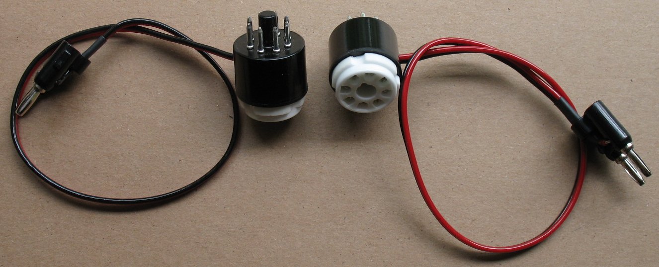 Assembled bias checkers |
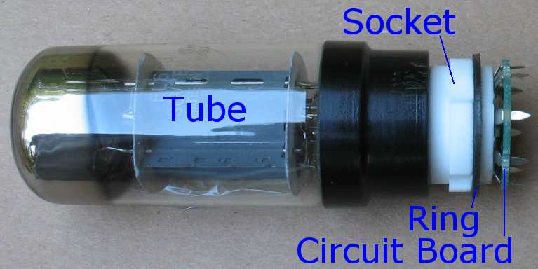
| How it works The way this Bias checker works is that pins 1,2,3,4,5,and 7 pass uninterrupted through the Bias Checker from the tube base to the tube socket. Pin 6 is not used in most 8 pin tubes and so there is no need to wire it up. Pin 8 from the tube base is sent out to a Multimeter set to dc milliamps and sent back to pin 8 of the tube socket. You are basically reading the current flowing through pin 8 by putting your meter in line with it. You can see the current flow in the diagram above left. The current flows up from pin 8 of the tube base, out through the multi meter and then from the multi meter to pin 8 of the tube socket. The meter is set to DC milliamps and the range is set to under 200 milliamps on the meter. Most amps will only be biased to under 50 milliamps per each power tube |
|
| Click on the images below for a larger image | |
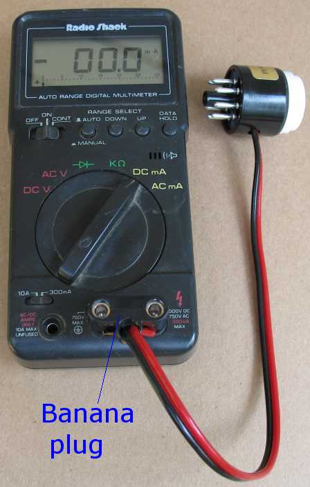 The banana plug plugged into a multi meter Note that some meters have different spacing and may not accept a dual banana plug You can use individual banana plugs to do the same thing on wider spaced meters |
|
| - | |
| How to assemble the Bias Current Checker | |
| Click on the images below for a larger image | |
 Insert a 8 pin tube into the 8 pin PC socket. This is done so that all the pins line up properly on the tube socket. You may not be able to get a tube into the socket later if you do not insert one now. Slide on the Ring now - If you forget to do this now, it will be too late later. I like to super glue the ring to the socket now, so it becomes part of the socket. The ring helps center the tube socket on the tube base and gives the tube socket a nice place to rest. Bend the tube socket pins so that they are straight up, so they will line up with the circuit board holes properly. |
|
| - | |
 |
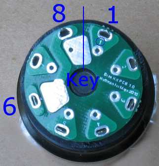 |
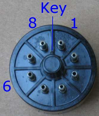
| The circuit board has small numbers for each pin The 8 pin PC tube socket has numbers on it also. Line up the numbers so they match and slide the circuit board onto the Tube socket pins. The key on your tube base and the key on your tube socket should be pointing between pin 8 and pin 1 on the PC board |
|
| - | |
 |
|
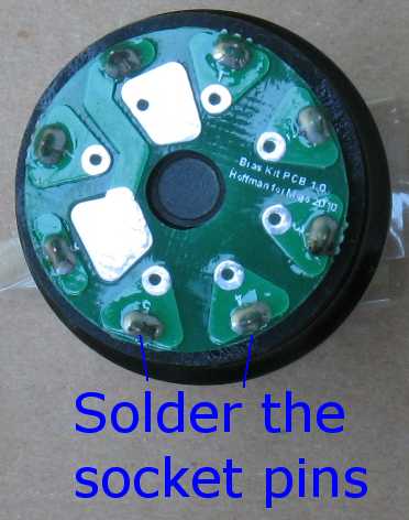
| Check to make sure you put the ring on Solder all the tube socket pins to the PC board |
|
| - | |
| Click on the images below for a larger image | |
 |
|
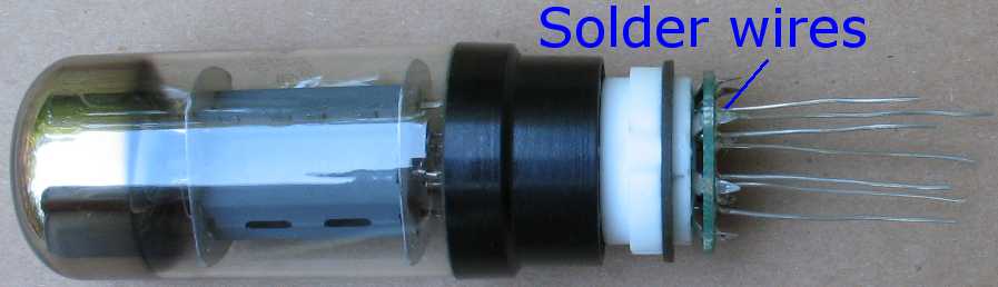
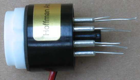
| The holes in the circuit board are drilled for 20 gauge wire Cut 7 pieces of 20 gauge wire about 2 to 3 inches long. See my tip below about wire lengths. Strip the insulation off the 20 gauge wire. Push the 20 gauge wires straight down into the 7 holes. There is nothing behind the board they can short out on, so just push till the wire stops. Make sure you do not angle the wires towards the tube socket pins Make sure you are not pushing the wire so hard that it bends under the circuit board and heads off at an angle towards another pin Look behind the circuit board and make sure you have not pushed the wire at an angle You do not want the pin 8 wire to contact the tube socket pin because that is the pin we are breaking so we can measure the current The 20 gauge wires should stand up in the air by themselves, which makes them easier to solder. Solder the 7 wires into the 7 holes on the circuit board. Pin 6 does not have a hole. The image further down the page shows the wires standing up in the air |
|
Tip: I like to trim the 7 x 20 gauge wires so that each one is a bit shorter than the next one. This makes it much easier to slide the wires into the tube base one at a time. This image is an exaggeration of the wire lengths Each wire is maybe about 1/8th inch shorter than the next |
|
| - | |
|
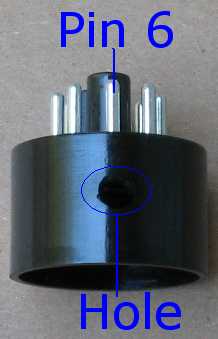 |
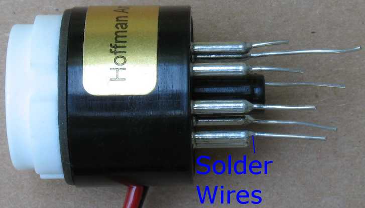
| The bases already have a wire hole drilled in the proper place. This hole is right in front of pin 6 Pin 6 is not used on most 8 pin power tubes and so this makes a great place for the wire to enter the tube base. Slide the wire into the hole in the base The images below shows what this looks like. |
|
| - | |
 |
|
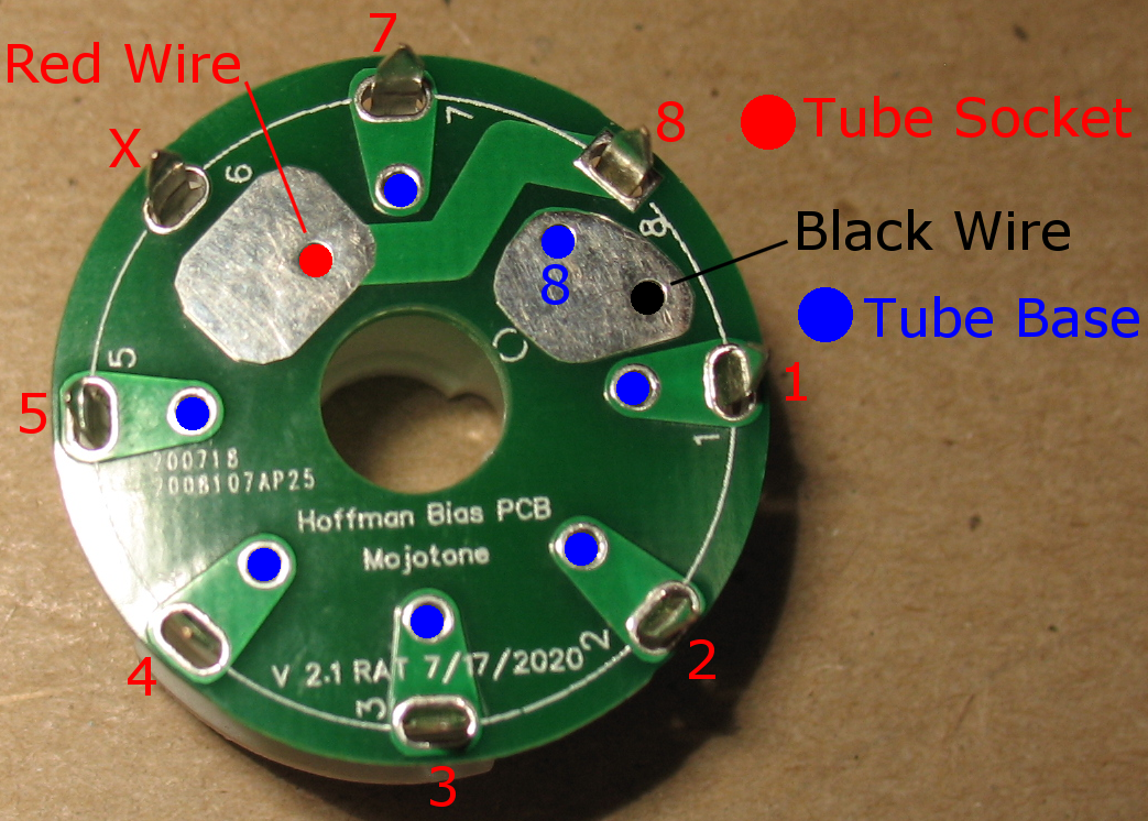
| Here's an updated image of how to make the
connections. A 8 pin tube socket is connected to the PCB board in the image above. The 8 pin tube socket and the tube base both have number on them. Red text goes to the tube socket pins. Blue circles go to the tube base pins via number 20 buss wires. There is no direct connection from Pin 8 socket to Pin 8 Base. The number 8 pin connection is only made through the Red and Black zip wires that are connected to a multi meter set to milli amps. Note that the older PCB boards look a bit different than current PCB boards. The connections are the same on both boards. |
|
| - | |
| Click on the images below for a larger image | |
 Strip the wire ends and solder the Black/Red zip cord to the circuit board. It helps if the Red wire is cut just a tiny bit shorter than the black wire. The black wire is soldered to the pad where pin 8 is. The red wire is soldered to the pad next to pin 6 Make sure your solder connections are clean and that there is no way a wire or solder blob can short out onto another part of the circuit board. Make sure you do not use too much solder and jumper across the circuit board sections. Tip: I like to bend the tip of the red wire at a 90 degree angle before I solder it. This keeps the red wire from getting too close to pin 5 |
|
| - | |
| Click on the images below for a larger image | |
 |
 |
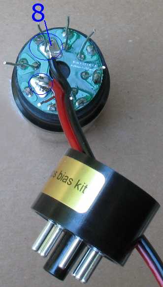
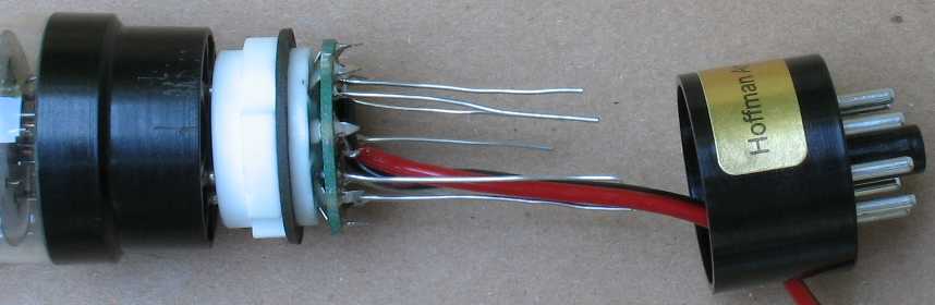
| Push the two sections together slowly This part can be a bit tricky so take your time. You have to rotate the tube base and the tube socket circuit board assembly so that pin 6 lines up in a straight line. Move the two items closer together and align all 7 of the 20 gauge wires so they go through the holes on the tube base. See my wire length tip because it makes this part much easier. The technique is to pull a bit of the zip cord, pull everything closer, pull some more zip cord, pull everything closer, etc It helps if you can guide the 7 wires into the tube base holes with a small set of needle nose pliers or some sort of dental pick device. When you get it right, the 7 wire tips will be sticking out the bottom of the tube base pins. Double check to make sure all 7 wires are in the correct holes in the tube base. After you have made sure the 7 wires are in the correct holes, push the whole assembly together tight. Tip: Before you solder, now is the time to make sure you have everything assembled correctly You can use a multimeter set to continuity to check the red and black wire connections. My multimeter beeps and this is very handy. These two points should have continuity 1 - The tip of the black wire and pin 8 on the tube base = continuity 2 - The tip of the red wire and pin 8 on the tube socket = continuity |
|
| - | |
| Click on the images below for a larger image | |
 |
 |
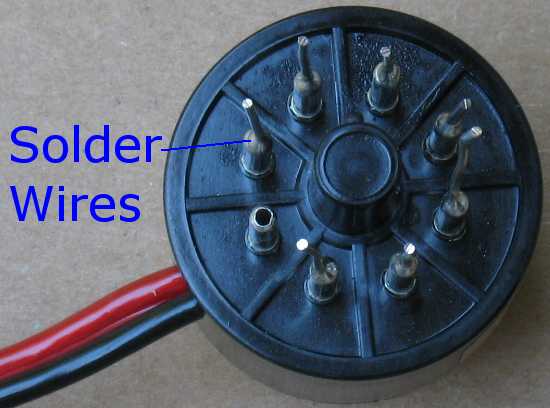
Solder all 7 wires to the tube base pins. You solder the wires by touching your hot soldering iron to the junction of the base pin and the 20 gauge wire. As soon as the junction is hot enough, touch your solder to the junction and it will follow the wire down into the tube base pin. You do not apply the solder to the outside of the tube base pin. It's a delicate operation and one that takes a bit of practice to get good at. Your soldering iron tip should be very pointy and very close to the tube base pin so that the pin gets just as hot as the wire does. The Solder will follow the heat, you do not have to stuff the solder into the hole.  Tips: I grind my soldering tips on a bench top sander to a fine point for this type of work. I take a piece of solder with me to the sander and my solder iron is already hot. I spin the tip on the sander to get a nice point. The tip is now copper colored so I quickly tin the tip with solder to get a nice clean, pointy tip. If you blob solder all over the outside of the tube base pin, you will not be able to push it into a tube socket on your amp. you may even damage a tube socket by trying to force an oversized pin into it. If you do blob a bit of solder on the pins, you can do this. Clean all the solder off the tip of your soldering iron with a damp cloth. Heat up the tube base pin and wipe the solder blobs off with a cloth while the solder is still hot. You can also use an exacto knife or razor blade to gently slice off the solder. It is way better to do it right the first time and not have to clean up a mess later |
|
| - | |
| Click on the images below for a larger image | |
 |
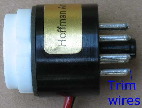 |
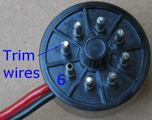
| Snip off all the 20 gauge wires after you have soldered them | |
| - | |
| Click on the images below for a larger image | |
 |
|
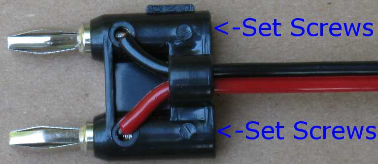
| Strip the ends of the black and red wires Tin the wire ends with a bit of solder Loosen both set screws on the banana plug. Push in the black and red wires. Tighten down the set screws. You can install the wires into the banana plug any way you like. If you plug it into your meter one way, you will be reading negative current flow If you plug it into your meter the other way, you will be reading positive current flow. If your meter only works one way, you will have to make a note which way to plug it into your meter. |
|
How to use the Bias Current Checker Plug your Bias Checker into a tube socket on an amp. Plug your power tube into the Bias Checker. Plug the banana plug into your Multimeter. Make sure you plug the banana plug into the two holes on your meter that are for DC current measurement. Set your Multimeter to DC milliamps in the under 200ma range. Turn on the amp and let it warm up in standby mode, if it has a standby. Take the amp off standby, but be ready to quickly put the amp back on standby if the current is too high. Turn the bias pot until you get somewhere around 35 milliamps of current. 35ma is a Generic bias setting, set your bias accordingly Put the amp back on standby Remove the bias checker and move it to the next tube. Put the first tube back into the tube socket. Check the next power tube and split the difference if they are off just a bit. You cannot check the bias properly unless all the power tubes are installed and running. Each power tube pulls a certain amount of current and this alters the overall voltage on the power supply. If you try and read the bias with some of the power tubes out of the amp, you will not get a proper current reading. Example of a bias reading If you have 38 ma on one tube and 34 ma on another, they are still close enough to be called a matched pair. If you are off more than 8 or 10ma, that is not a real good matched pair but the amp will work. I have seen some Fenders be way off and still sound awesome. Different current readings between each of the power tubes can be caused a couple different things. It could be the tubes themselves or the parts connected to each tube socket can alter the current readings. You must swap the tubes around and read them in different sockets to figure out what is going on. If a tube reads differently in a different socket, then you can assume it's not the tube. Screen grid resistors can drift and cause altered current readings. The output transformer windings can also be the problem. The bias supply can be sending different negative voltage levels to each tube. If your amp has fixed bias but it does not have a bias pot If you do not have a bias pot, you will have to figure out where the fixed resistor is in the bias circuit that controls the negative bias voltage. It is a resistor that will be able to read the negative bias voltage on one end and is connected to ground on the other end. You have to change the bias resistor to a larger value for less bias current (more bias voltage) and a smaller value for more bias current (less bias voltage). This page will not be able to cover all situations you may run into on a bias circuit that may need to be modded Please go to the Hoffman Amplifiers tube amp forum for help, the people on my forum are very knowledgeable. If your amp is cathode biased You don't really need a bias checker, but you can use one if you want to get a more accurate picture of what is going on. You can measure the voltage across the cathode resistor and do some math. Measure the voltage on the cathode resistor where it connects to pin 8. Divide that figure by the value of the cathode resistor Both power tubes usually go through one resistor, so you divide that figure in half to see each power tubes current. Here's an example: Two 6V6's in a Fender share a 470 ohm cathode resistor You measure 22 volts DC on pin 8 of either power tube. Divide 22 volts by 470 ohms = .0468 amps Divide that by 2 to get each power tubes current and you get .0234 amps Each power tube is flowing 23.4 milliamps of current Of course, one power tube may be pulling 20 milliamps and one 26 milliamps. The bias checker can tell you more accurately what each tube is doing. Multiple bias checkers One bias checker for each power tube in your amp would be the ideal situation. Switching the amp on and off and moving the bias checker around is less than ideal. The problem with this is that you have to have some sort of switching situation that re-connects a tube after you switch to the next tube. I made such a thing years ago after finding a multiple push button switch that was able to switch properly. You could also have multiple meters running it's own bias checker and read multiple tubes at the same time. There is more info on biasing on the library page. |
|
Enter My Tube Amp Parts Store Here
Mobile users Enter My Tube Amp Parts Store Here
The Tube amp Library of information
Click the link above for Tube amp info, Schematics, Board building information, Projects, Mods, Transformer diagrams, Photo's, Sound clips.
There are hundreds of pages of Tube amp information on my library page.
Please visit my Tube Amplifier Forum
Here's the place you can go to ask tube amplifier questions.
You will find a large community of friendly amp builders at the link above.
Check the huge library of Schematics here
Design your own custom Turret Board or Eyelet board
DIY Layout Creator file analyzer program
DIY Layout Creator file library
How to email me
|
MEMBER OF PROJECT HONEY POT Spam Harvester Protection Network provided by Unspam |