
Clicky switch mod |
|
| - | |
|
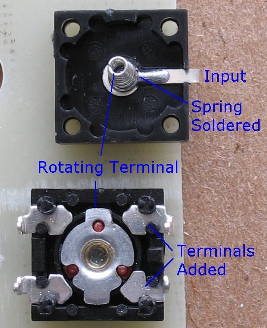
This page shows how to improve the clicky switch that is used in many of my LED projects. One of the main problems with the stock switch is that the internal contact surfaces are small. What I am doing here is adding two more contacts so that the contact surface is doubled. This improves the current handling capacity and the reliability of these switches. The only way to take advantage of this mod is to jumper each of the two sets of terminals together. This doubles the output path out of the switch. It also insures that if one of the terminals is not making good contact, the other one probably is. I am now cutting some of my circuit boards to take advantage of this mod. The switch board has jumpers that jumper the new terminals together. I am also soldering the input spring to the input terminal to improve this connection. This is a very precise solder joint. You must have a very sharp solder tip and a steady hand to pull off this solder joint. You will need two of the clicky switches to do this mod. You are using two contacts from one switch and adding them to the other switch. You must pry these switches open very carefully to avoid damaging the outer casing. When you re-assemble the switch, use a tiny bit of super glue on all four corners to make sure the switch stays together. How the switch works The battery negative is connected to the Input terminal. The battery negative current flows through this terminal and then through the spring. The spring touches the center of the rotating switch terminal. When the rotating switch terminal touches any of the other terminals, the battery negative current flows out those terminals. There are actually 6 click positions for each rotation of the center terminal. The switch basically duplicates the 3 - switch clicks twice for every rotation One 360 degree rotation looks like this. Off-on-on-Off-on on The switch in the photo's below appears just like it does in my resistor board assembly page. If you are looking at the back of my resistor circuit board with the notch facing up, you can see exactly which terminals are switched on first. |
|
| - | |
| Click on the images for a larger image | |
 |
 |
|
Here you can see I have added two more terminals. You can also see that I soldered the Input spring to the Input terminal |
Here is what the switch terminals look like when the switch is off. The center terminal is not touching any of the other terminals |
| - | |
| Click on the images for a larger image | |
 |
 |
|
Click the switch once and now two terminals are on. This is the first on position when used on my copper circuit boards |
Click the switch once again and the other two terminals are now on. This is the second on position when used on my copper circuit boards |
| - | |
| Go back to the main bike lights page for more Marwi mount info | |
| Back to Bike lights page | |
| - | |
Enter My Tube Amp Parts Store Here
Mobile users Enter My Tube Amp Parts Store Here
The Tube amp Library of information
Click the link above for Tube amp info, Schematics, Board building information, Projects, Mods, Transformer diagrams, Photo's, Sound clips.
There are hundreds of pages of Tube amp information on my library page.
Please visit my Tube Amplifier Forum
Here's the place you can go to ask tube amplifier questions.
You will find a large community of friendly amp builders at the link above.
Check the huge library of Schematics here
Design your own custom Turret Board or Eyelet board
DIY Layout Creator file analyzer program
DIY Layout Creator file library
How to email me
|
MEMBER OF PROJECT HONEY POT Spam Harvester Protection Network provided by Unspam |