
2800ma Multi Mode driver board
I use this driver board to assemble the Marwi XML LED bike lights |
|
| - | |
|
This page shows all the parts I use to assemble the XML lights This page has the assembly instructions for the Marwi XML lights |
|
| - | |
 |
|
|
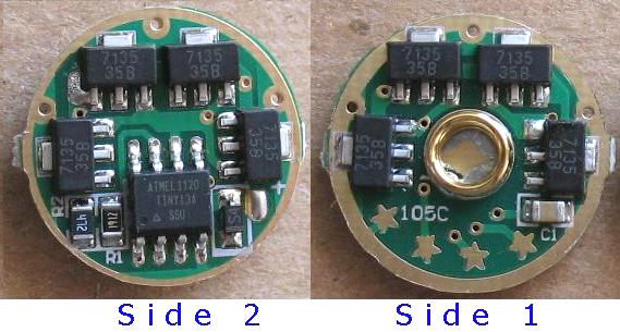
This driver board has 8 AMC7135 current limiter chips There are 4 x 7135 chips on Side 1 and 4 x 7135 chips on Side 2 Each chip can limit 350ma of current 8 x 350ma = 2800ma total current limit capability There is also a micro controller chip that pulses a control leg on the 7135 chips This is how the board can deliver different current limiter modes The micro controller pulses the control leg at different rates to increase or decrease the current |
|
| - | |
 Click for a larger image |
 |
|
See the diagram above right that explains the different modes The stock board is already set to Mode 1, no stars are grounded You do not have to select a different mode if you want a strobe and SOS mode What appears to be Star #1 is just a Star that is connected to the outer ground ring If you want to select another mode, you have to ground one of the stars Stars #2, #3 and #4 are the mode selecting stars Solder a small wire from one of the stars to the outer gold ground ring to select which mode you want to use I like Star#3 mode because it gives you 3 different light levels without the annoying strobe and SOS modes You use a regular SPST On-Off switch to control this board This switch interrupts the Battery - on it's way to the board To turn on the LED, you click the switch so that the Battery - is now connected to the board. To change modes, you push the switch lightly until the switch contacts are no longer connected. Then you release the switch to reconnect the contacts The board switches to the next mode You do not have to click the switch, just tap it lightly To turn off the LED, you click the switch so that the Battery - is disconnected from the board The board remembers the last mode when you shut it off and turn it back on Use the diagram above left to follow the color codes described below. The gold ring that surrounds the outer part of the board is Battery minus or ground. If you solder a small wire from Star #3 to the outer gold ring, you are selecting mode 3 The green colored squares on the diagram above are Battery - or ground Star 1 is just a star that is connected to ground The Red dots are Battery Plus and LED plus (same thing) The yellow squares show how the Stars are connected to the controller chip The yellow stars are where you solder your jumper wire to select the mode you want The Orange squares show how the micro controller chip is connected to the 8 x 7135 chips The Orange legs on the 7135 chips are pulsed on and off to regulate the current at different levels. Assembly tip if you are using mode 3 I use mode #3 on the Marwi XML light I build You can take a quick time saving short cut and solder a small blob of solder across the TINY13A chip legs to select mode 3 The two legs you use are the yellow #3 leg and the green leg to the right of yellow #3 See the picture above left that shows these two legs The assembly page link at the top of this page has pictures of how I do this |
|
| - | |
 |
|
|
This is how you hook this board up to a Battery and a LED Note that Battery + and LED + are the same thing I like to connect Battery + and LED+ to the gold spring because it's easier to solder to this large area There is a small solder pad with a + sign. You can use that pad for LED+ if you want to Battery - can be soldered to the outer gold ring on any side of the board that you want. Normally Battery - goes to a SPST On-Off switch first and then from the switch it goes to the board This is how you turn the LED Off and on and change modes The LED- solder pad is very tiny and can be tricky to get a wire soldered to it. It takes a very fine tipped solder iron tip to do this Do not blob solder everywhere and short out across other solder traces. You are very close to the outer Battery - ring on the boards so be careful. Never solder a wire to a trace and then try and bend the wire a different direction You will rip the copper solder trace right off the board, or worse yet, rip a chip off the board |
|
| - | |
Enter My Tube Amp Parts Store Here
Mobile users Enter My Tube Amp Parts Store Here
The Tube amp Library of information
Click the link above for Tube amp info, Schematics, Board building information, Projects, Mods, Transformer diagrams, Photo's, Sound clips.
There are hundreds of pages of Tube amp information on my library page.
Please visit my Tube Amplifier Forum
Here's the place you can go to ask tube amplifier questions.
You will find a large community of friendly amp builders at the link above.
Check the huge library of Schematics here
Design your own custom Turret Board or Eyelet board
DIY Layout Creator file analyzer program
DIY Layout Creator file library
How to email me
|
MEMBER OF PROJECT HONEY POT Spam Harvester Protection Network provided by Unspam |