
Behringer FCB1010 Mods - External power source with integral Midi interfaceBack to the main Sound page |
|
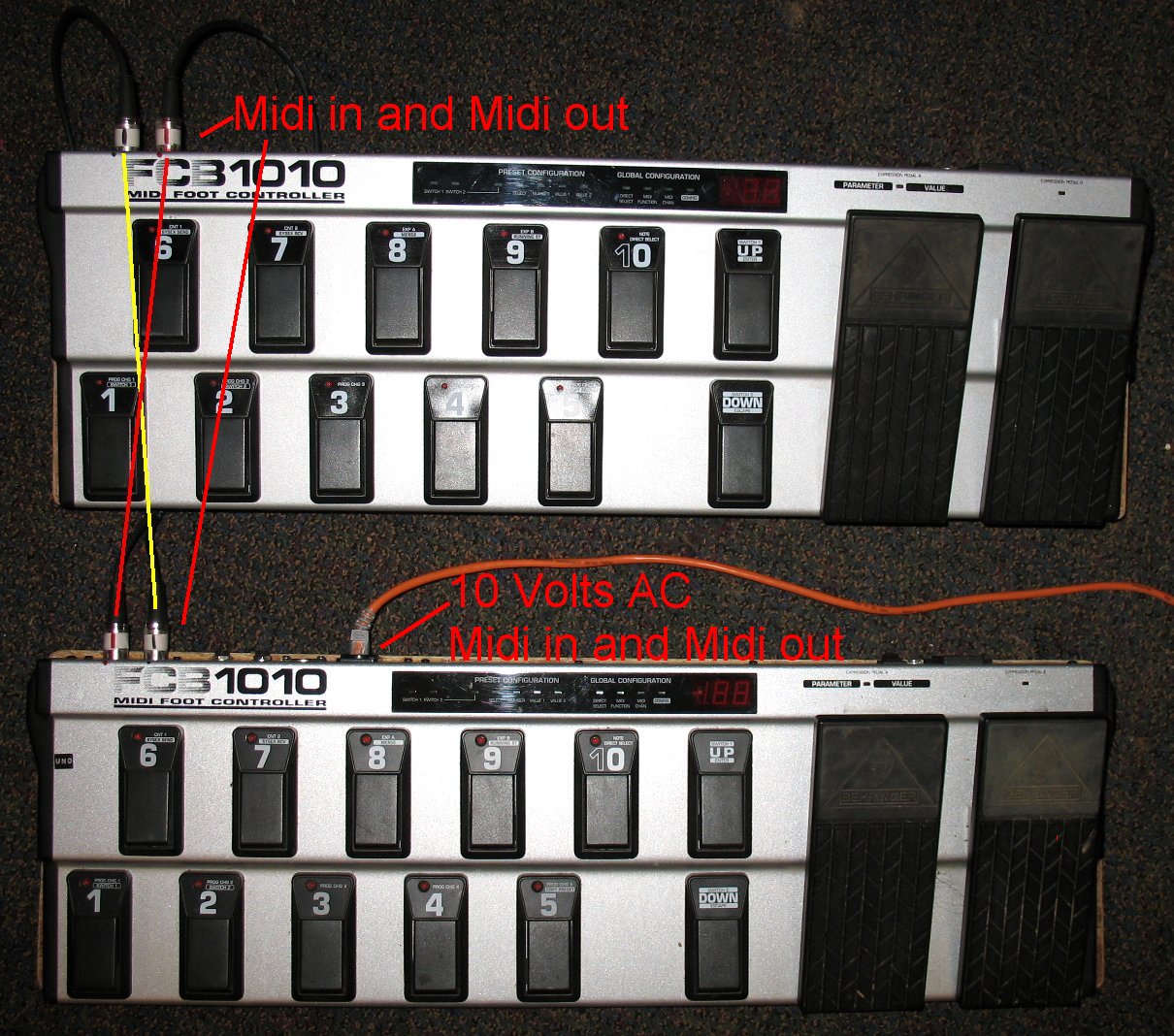
| This page describes how I created an external power source for my two Behringer FCB1010 midi controllers The external black box that holds the power source also holds a USB Midi interface A stock FCB1010 has an AC power cord that brings power into the FCB1010 You also need two midi cables to send and receive Midi data So that's 3 cables laying on the floor for one FCB1010 I have two FCB1010's and so that is 4 cables total on the floor You can put the two FCB1010's in Midi series with a short Midi cable The FCB1010 internal power transformer creates 10 volts AC from a wall socket source It is possible to bring 10 Volts AC into the FCB1010 from an external power source and not use a AC power cord If you only have one FCB1010 you could use two wires inside a midi cable to bring in that power In a Midi cable there are typically 4 wires Only two of those wires are used for Midi signals So you can use the other two wires to bring power into the FCB1010 This is what many people do and you can find several of those projects on the web The way I am doing it is by bringing the 10 Volts AC via a CAT 5 network cable The reason I am using CAT 5 cable is that it has 8 wires I have two FCB1010's so that requires that I have 4 Midi data wires So that leaves 4 wires free to use for power I only need two wires for power but it is a good idea to combine two wires to get a larger current capacity The four extra CAT5 wires are joined together to make two pairs of wires And since the power I am sending down the CAT5 cable is AC, I used two twisted pairs to send 10 volts AC Twisted pairs of wires cancel out hum and so I am just being cautious CAT5 network cable has 4 twisted pairs of wires inside And since I have two FCB1010's, I am going to remove one of the power transformers in one of the FCB1010's This power transformer will be used to power both FCB1010's in my external power box The power transformers in FCB1010's are beefy enough to supply power to two FCB1010's The power transformer will be mounted in an external box next to all my gear A single CAT5 cable will come from the box near my computer and sound gear to the FCB1010's That's it, just a single CAT5 cable on the floor I am also adding a USB to Midi interface inside my FCB1010 power box The power box will have a USB cable that will go to the computer The USB Midi adapter wires will go to a RJ45 jack The RJ45 jack will send and receive Midi info to and from the FCB1010's So my power box not only makes 10 volts AC for the FCB1010's, it also sends and receives Midi data from the computer to the FCB1010's Everything is in one small box The image below shows just how clean my dual FCB1010 setup is now |
|
| Click on the images to see a larger image | |
 |
|
| One CAT5 network cable enters the bottom FCB1010 The network cable wires carry the 10 volt AC power, the Midi in and Midi out signals The bottom FCB1010 has two short Midi jumper cables that connect to the top FCB1010 The bottom FCB1010 sends 10 volts AC to the top FCB1010 through two short the Midi jumper cables The two short midi cables that join the two FCB1010's are hooked up like this: Midi out/thru on the bottom FCB1010 goes to Midi in on the top FCB1010 Midi out/thru on the top FCB1010 goes to Midi in on the bottom FCB1010 Note that the bottom FCB1010 has the UNO chip and it has 5 stomp box pedals That's the FCB1010 I decided to do the major mods to because it has already been modded The top FCB1010 is a stock FCB1010 except for the simple power in wires I added That simple mod is described further down this page |
|
| - | |
| Click on the images to see a larger image | |
 |
|
| The mod info on this page may be a bit confusing to some This simple diagram illustrates how the black box connects to the computer and FCB1010's |
|
| - | |
| Click on the images to see a larger image | |
 |
|
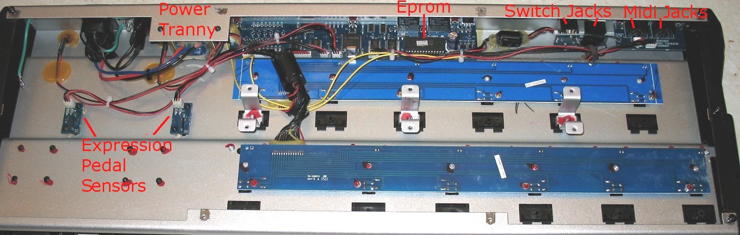
| Full view of the insides of a FCB1010 The power transformer is on the upper left There are two yellow wires that leave the power transformer and go to some diodes The diodes rectify the 10 volts AC into DC The Midi in and out jacks are on the upper right |
|
| - | |
| Click on the images to see a larger image | |
 |
|
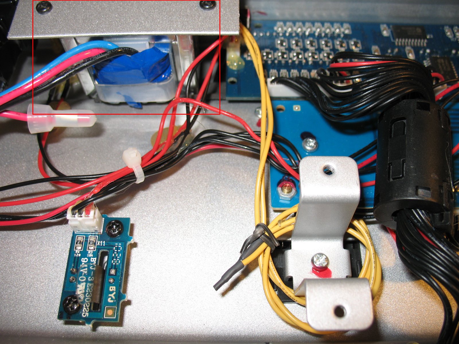
| The image above shows the power transformer in the upper left This is my #2 FCB1010 that receives power from the 1st FCB1010 I have clipped the yellow wires from the diodes and heat shrinked them because I am going to use external power full time in this unit |
|
| - | |
| Click on the images to see a larger image | |
 |
 |
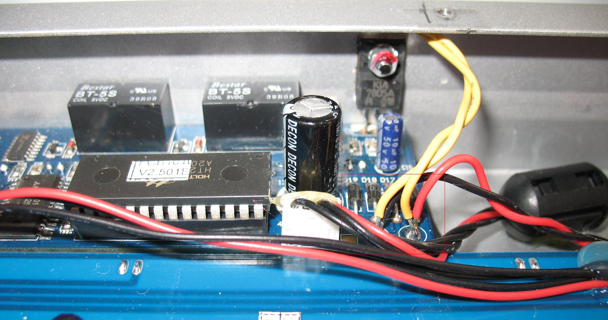
| Left: In a stock FCB1010, the yellow wires from the power transformer go to 4 diodes. The diodes rectify 10 volts AC into DC Note that in this image I have added a red and black wire that are not part of a stock FCB1010. The red and black wires are going to bring 10 volts AC to the diodes from an RJ45 jack I will add another red and black wire so that I can send 10 volts AC to my second FCB1010 through a MIDI jack The 2nd FCB1010 does not have to have a power jack because I can use two of the Midi cable wires Only one of my FCB1010's will have a RJ45 input jack |
|
| - | |
| Click on the images to see a larger image | |
 |
|
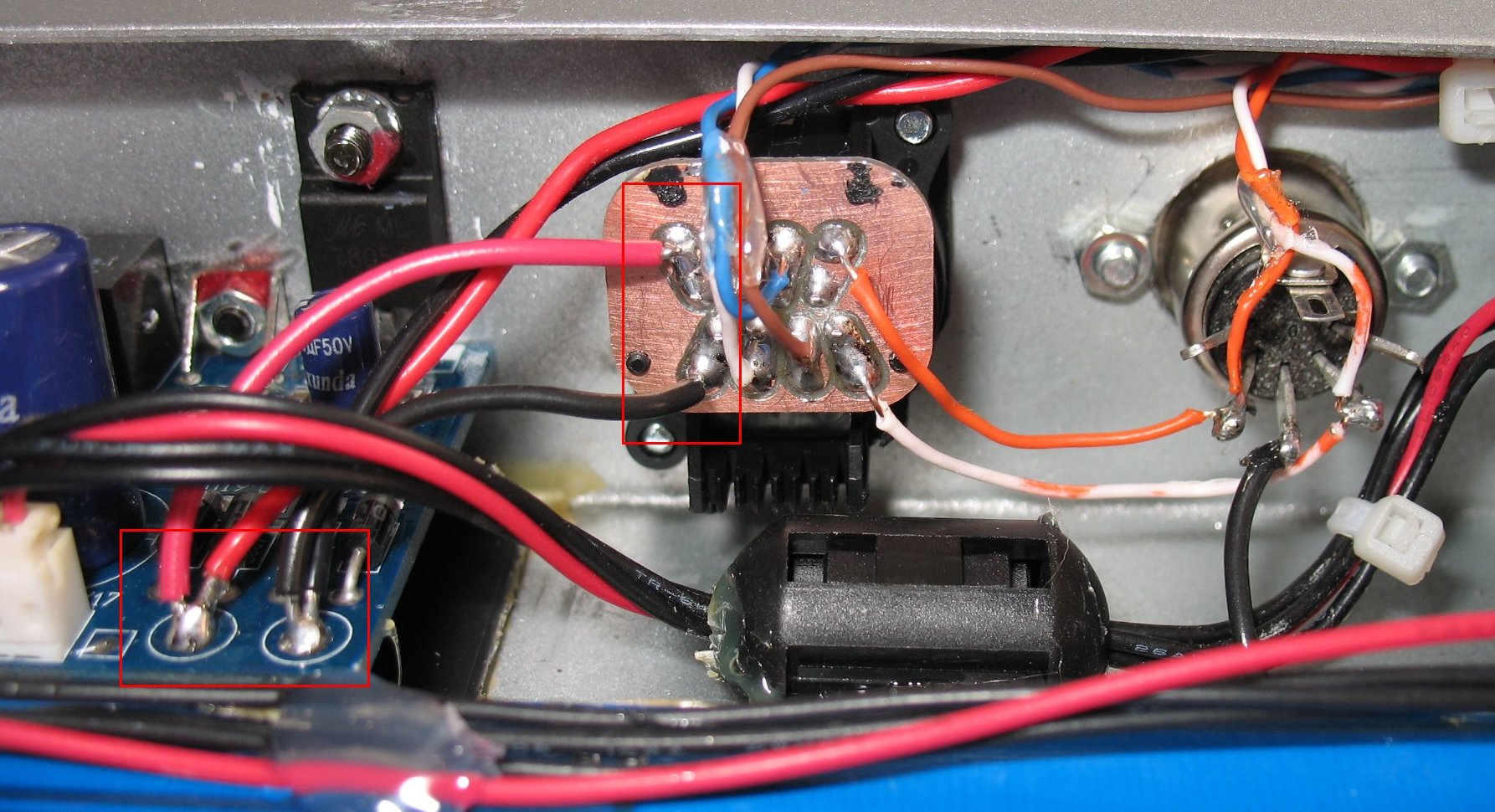
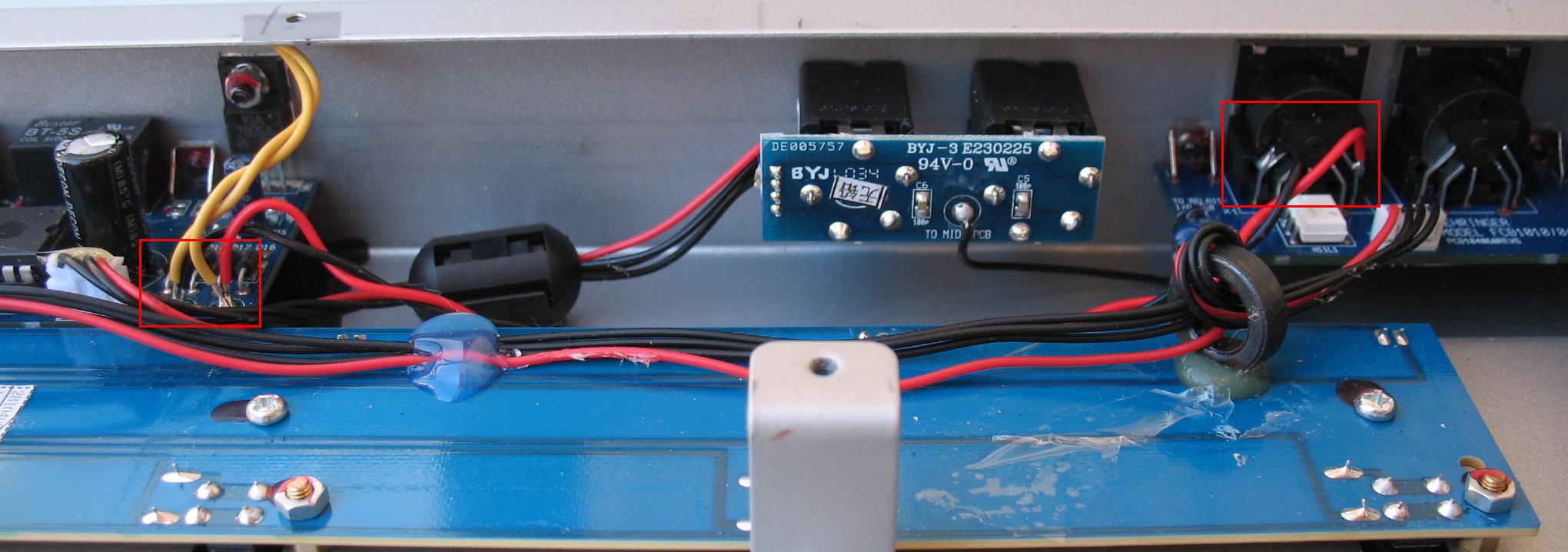
| This is the FCB1010 that has the RJ45 input jack The back of the RJ45 jack is shown in the center It has a small copper PC board on it so you can make solder connections to the 8 wires I have added a second pair of red and black wires to the diodes One red/black pair goes to the RJ45 jack The other red/black pair goes to the Midi in jack A Midi cable will then carry 10 volts AC to the 2nd FCB1010 Ignore the silver colored Midi jack to the right of the RJ45 with the two orange wires That is another experiment and is not part of my dual FCB1010 power mod |
|
| - | |
| Click on the images to see a larger image | |
 |
 |
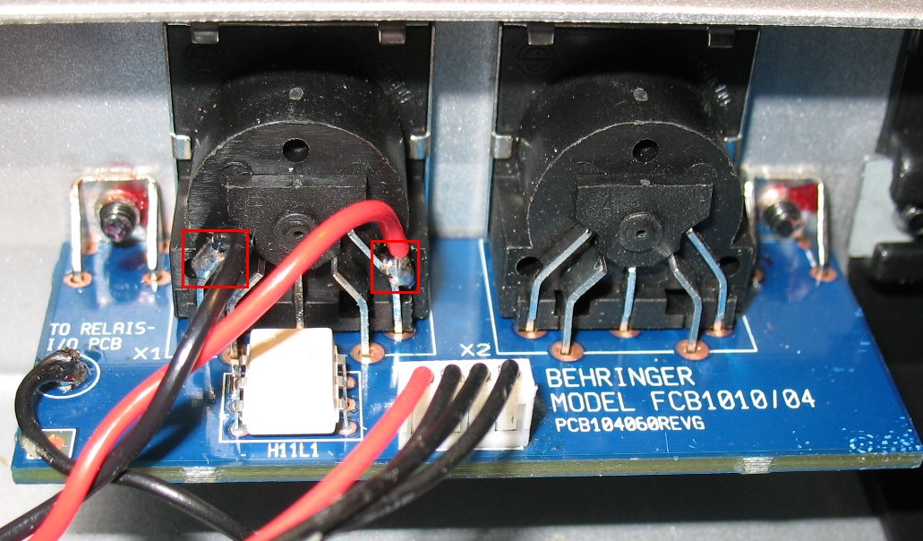
| This is the #2 stock FCB1010 that will get power from the 1st FCB1010 The 10 volts AC comes in through a Midi jack and then goes to the diodes The red boxes on the images show the connection points If you look at the image above left you can see which to pins I am using on the Midi jack Note that since this is AC, the wire connections do not matter I only used red and black wire because that is what I had one hand This is also how you would mod a single FCB1010 to use external power I describe how to do that below 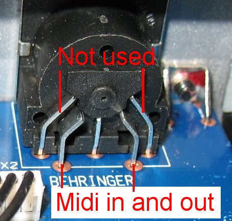 Single FCB1010 power mod If you had only one FCB1010 and you wanted to bring in external power, this is how you would do it You would use two wires inside a Midi cable to bring in the 10 volts AC You use the two outside pins on the midi in jack The other two pins are the Midi signal Ignore the center pin, it is a ground pin that provides ground to the shield on the Midi cable If you are going to use an external power source full time, I would unsolder and heat shrink the two yellow wires that go from the diodes to the power transformer Just leave the yellow wires coiled up and out of the way so you can easily convert the FCB1010 back to stock See the image further up this page showing the yellow wires clipped and heat shrinked You can remove the existing power transformer and use it in your external power supply or you can leave the stock power transformer in place and find a suitable power transformer that produces 10 volts AC |
|
| - | |
| Click on the images to see a larger image | |
 |
|
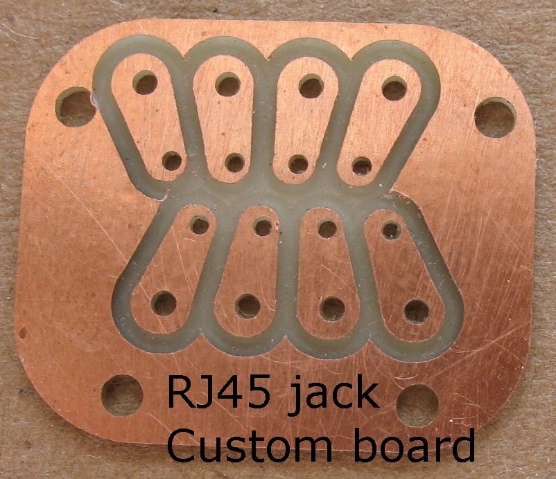
| This image shows the custom RJ45 jack pc boards I made on my CNC machine There were only tiny pc board pins on the jack and so I had to have a way to solder wires to those tiny pins |
|
| - | |
| Click on the images to see a larger image | |
 |
|
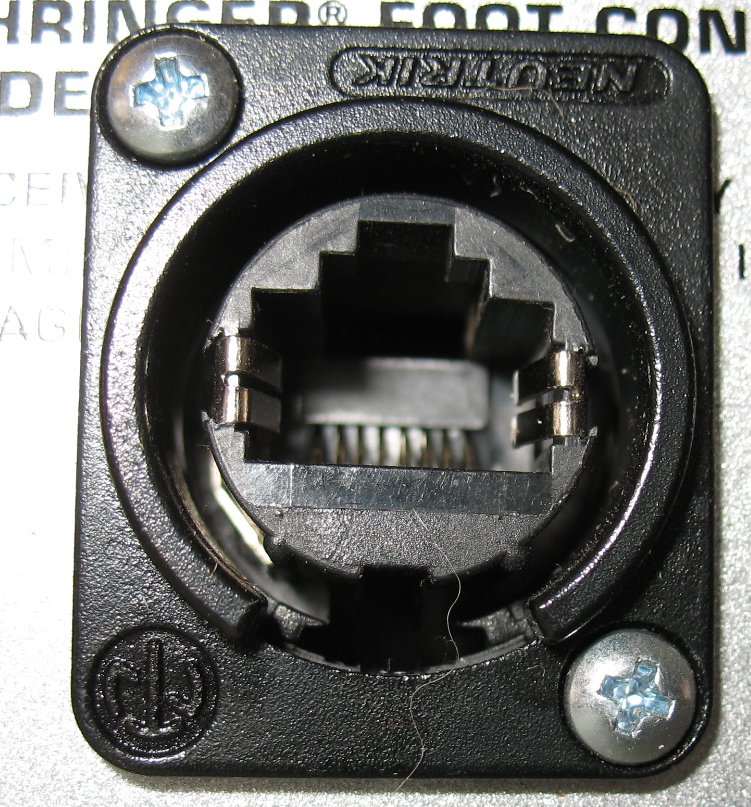
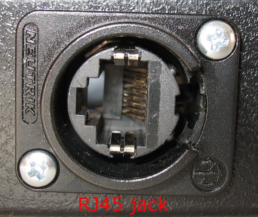
| This image shows what the front side of the RJ45 Neutrik jacks look like I used a step drill bit to cut a round hole in the FCB1010 chassis and then mounted the RJ45 jack |
|
| - | |
| Click on the images to see a larger image | |
|
|
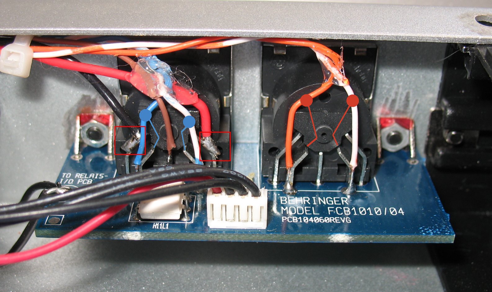
| Left: This image shows the red/black power wires going to the outside pins on the Midi in jack The connections to this jack are described further up this page This image also shows the Midi in and Midi out wires that go to the RJ45 jack The orange dots, lines and wires are connected to the Midi out jack The blue dots, lines and wires are connected to the Midi in jack Right: The orange and blue wire pairs on the Midi jacks go to the RJ45 jack These two pairs of wires then go to the USB Midisport inside the black box and then to the computer |
|
| - | |
| Click on the images to see a larger image | |
 |
|
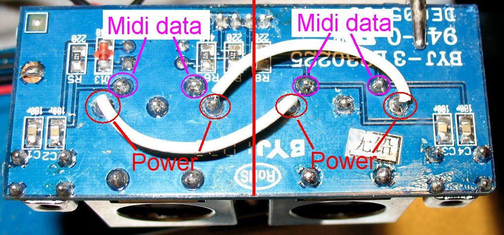
| I also jumpered together the outside pins on the Midi in and Midi out jacks in the modded FCB1010 so that both jacks can send
power I did this on the underside of the Midi jack board because it was easier than adding more wires to the back of the jacks The image above shows the underside of both Midi jacks The two inside connections on each Midi jack are Midi data The two outside connections on each Midi jack are used to supply 10 volts AC power |
|
| - | |
| Click on the images to see a larger image | |
 |
 |
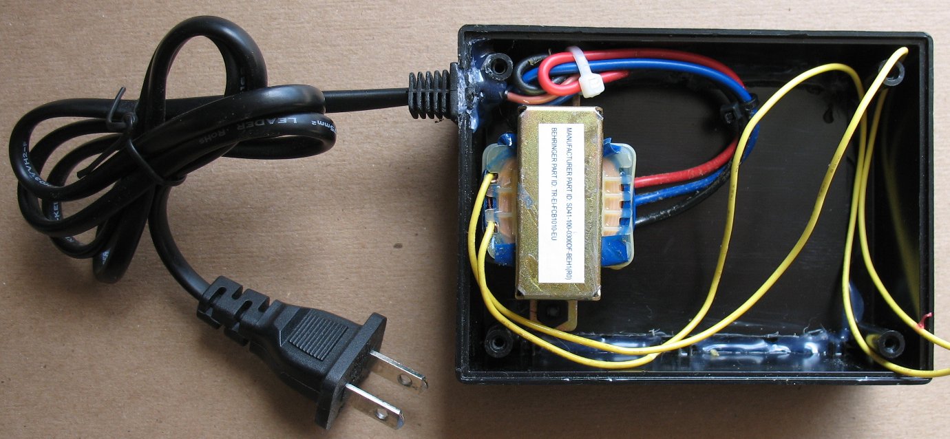
| I mounted the FCB1010 power transformer in a black plastic box and added a small power cord I used a step drill bit to make a hole for the RJ45 jack and mounted it on the side of the box |
|
| - | |
| Click on the images to see a larger image | |
 |
 |
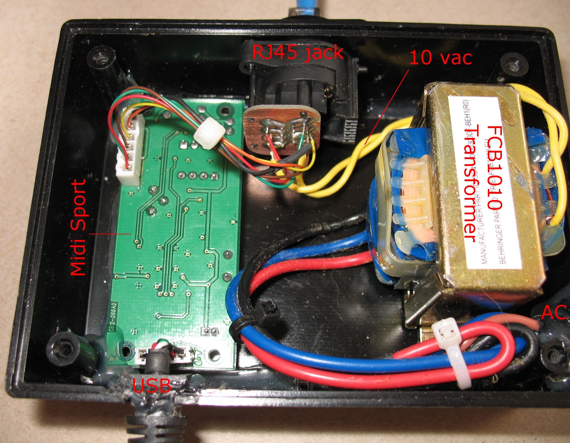
| I dismantled a M-Audio USB Midi sport and mounted it in the box A USB cable enters the box and goes to the Midisport board The wires leaving the white connector on the USB Midisport go to the RJ45 jack to send and receive Midi from the FCB1010's So now this little black box does all this: It provides 10 volts AC to the FCB1010's via the RJ45 jack It sends and receives Midi in and Midi out data to the FCB1010's via the RJ45 jack It sends and receives Midi in and Midi out data to the computer through the USB cable |
|
| - | |
| Click on the images to see a larger image | |
 |
|
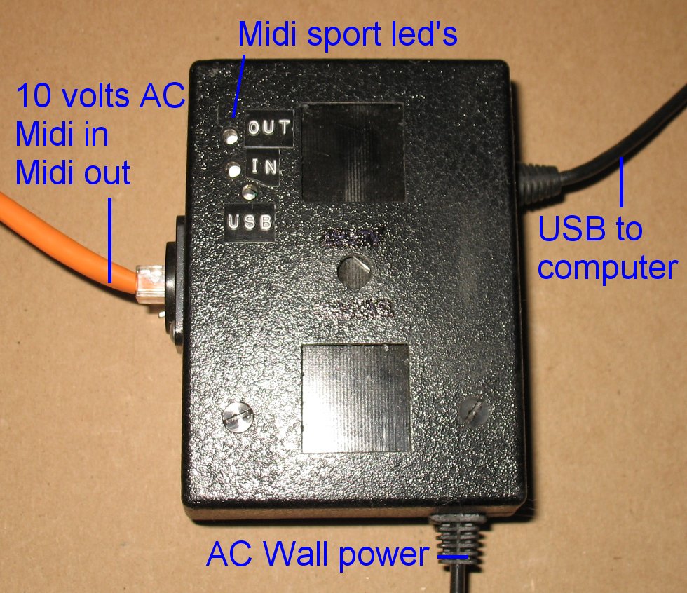
| Here's the little black box It used to be a surge suppressor in it's previous life Note that I drilled 3 small holes so the LED's on the Midisport would be visible The USB LED is lit up when the Midisport is connected to the computer The in and out LED's light up when Midi data is being transmitted |
|
| - | |
| Click on the images to see a larger image | |
 |
|
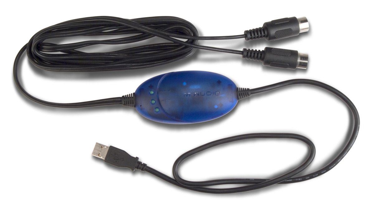
| This is the M-Audio USB Midisport interface that I installed in my black box The blue cover comes apart quite easily Use a multimeter to find out which pins on the circuit board are for Midi in and Midi out The Midi plugs are labeled as in and out If you use a beeping continuity meter you can touch a probe to a pin on a Midi jack and find that same pin on the circuit board Write down the wire colors and info to make yourself a wiring map Then you can map out those wires and connect them to the RJ45 jack in the black box When the wires enter the FCB1010, you can then send them to the proper Midi jack on the FCB1010 Here's a Midisport link on the M-Audio web site http://www.m-audio.com/products/en_us/Uno.html |
|
| - | |
| Click on the images to see a larger image | |
 |
|
| This is a schematic of the two Midi jacks inside the FCB1010 All the parts shown in the schematic are on the small circuit board under the Midi jacks |
|
| - | |