
| Back to Library page |
Cool amp tools |
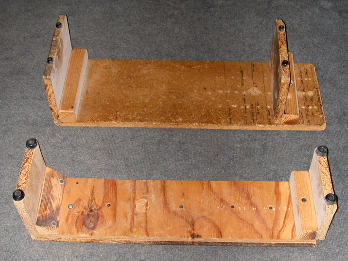 |
| These are the amp cradles that I use to set a chassis on so the tubes didn't get damaged while working on the amp You just move the right end piece by unscrewing a screw and then sliding the right end piece in. Rubber bumpers on top keep the chassis from sliding around. Note the top cradle has markings for all the different Fender chassis. |
| - |
|
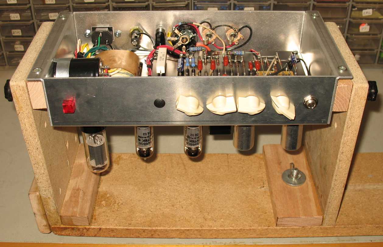
| Click on the image above for a larger image I built myself a new amp cradle that tilts and adjust for different chassis lengths I have a bunch of photos and build into on Facebook here. Amp Cradle info on Facebook |
| - |
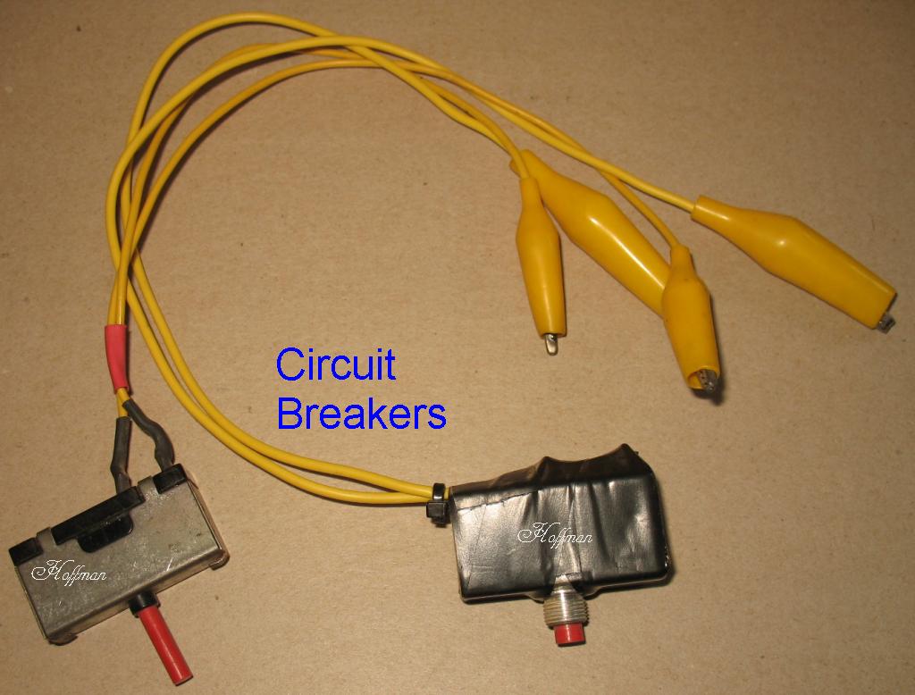 |
These devices are circuit breakers with alligator clips soldered on. When you are dealing with an amp that is blowing fuses, this tool is the thing to have. You just press the reset button after the amp has had it's way with you and you are on your way again. You can find these devices in old junk gear and at ham fest. They come in different amp ratings |
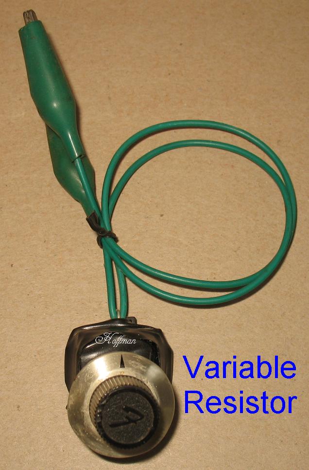 |
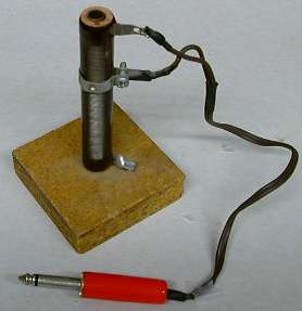
This device is a pot that you only use as a variable resistor. You use one outside leg and the middle lug of the pot to dial in a specific resistance value. After you find the value that works for you, you replace the pot with a fixed value resistor. The value of the pot can vary depending on what you are trying to dial in. A 1meg pot gives you a huge range but a tiny turn can be a huge resistance change. |
 |
Dummy load resistor: This is a large power resistor that you can vary a tap point on. There is sliding tap point that you can screw down anywhere along the body of the resistor. I think I have this one set at around 8 ohms. They get very hot when testing an amp so you need a very high power rating and it should not be able to touch anything. This one is probably 50 to 100 watts. |
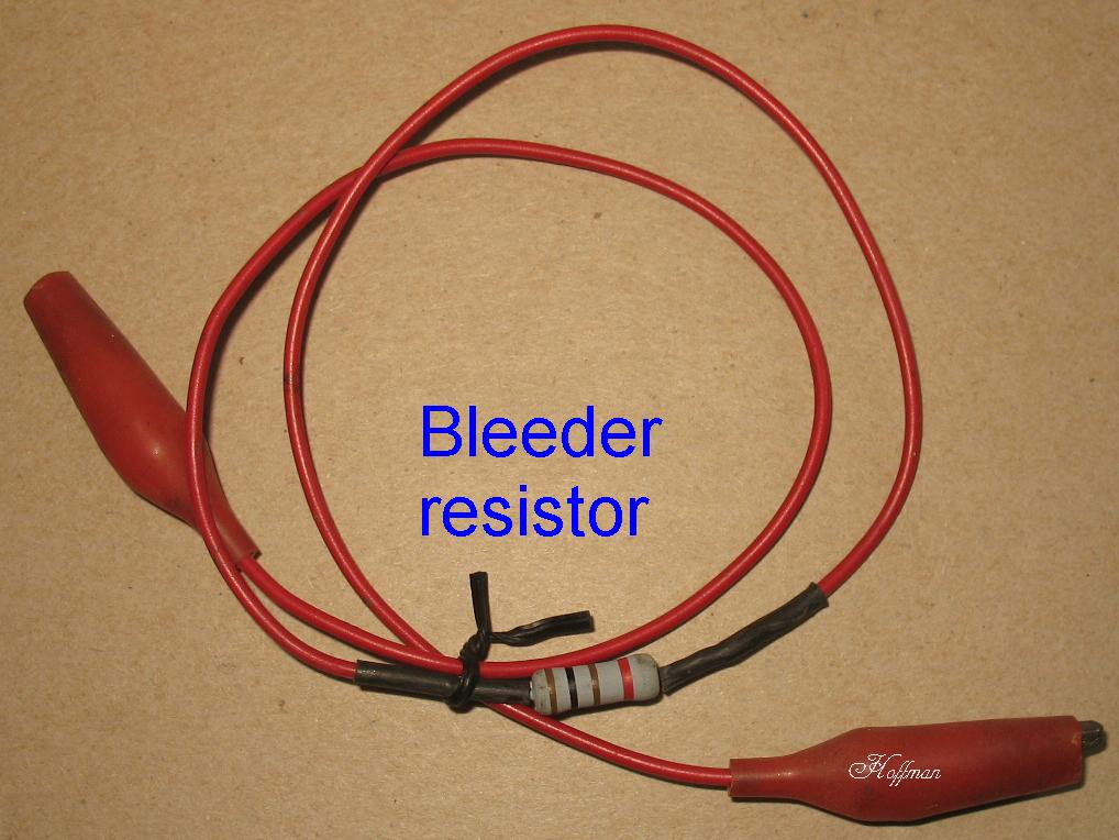 |
This is a simple tool used to drain filter caps and voltages from parts of the amp you are working on. Just a power resistor soldered between two alligator clips |
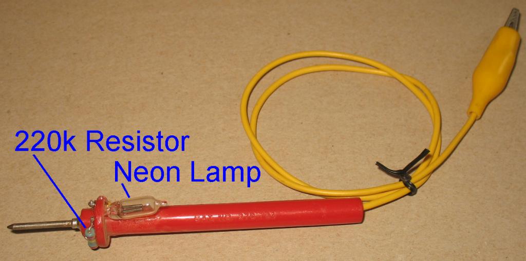 |
This is a probe you can use to probe AC voltages in the amp It's a 220k resistor in line with a neon bulb |
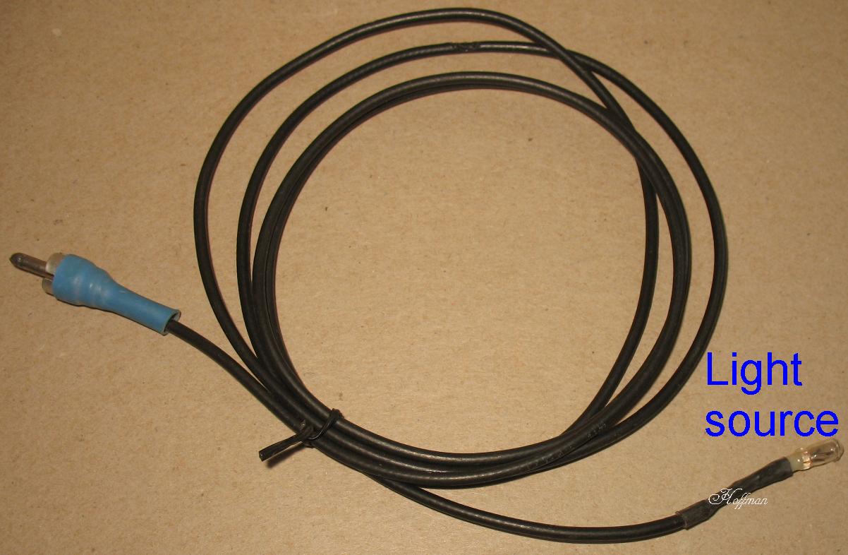 |
This is a small light bulb on the end of a cable. I used this to get a light source down inside tight dark places |
|
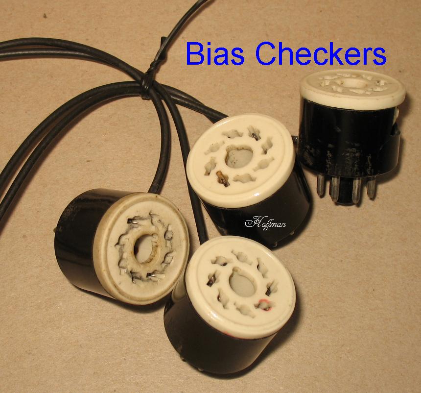
These were my original bias checkers that I made and used on my bench They have long since been retired. I sell new versions of these tools on this page I had a 4 way switching box that these plugged into and a current meter plugged into that box also. By pushing one of 4 buttons, the current would be switched through a bias checker. The switches were inline make before break When you pressed a switch, it would restore all the other switches to closed, and then it would open the switch you pressed and the current would be routed out through one of the bias checkers The new Bias Checkers I sell look like this 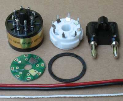 |
| Click on the image to see a larger image |
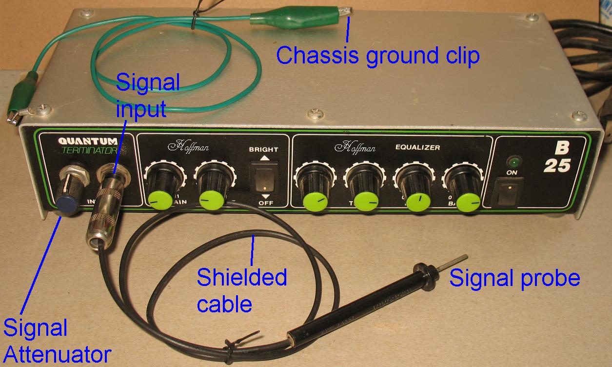 |
| This was my favorite tool besides my multi meter. This is a stethoscope listening amplifier that is able to probe a test amplifier and listen in on the signal as it travels from input jack to speaker jack. The listening amplifier pictured above is just a cheap solid state bass combo amp that I pulled out of it's cabinet and put an aluminum cover plate on. You want a clean sounding listening amplifier because you want to listen to the signal in the test amp and get an accurate picture of how the signal sounds. You do not want the listening amplifier to distort the signal. You could probably use an any audio amplifier. The listening amplifier is hooked up to a speaker cabinet so you can hear what is going on in the test amp. The test amp is hooked up to a dummy load because you do not want to hear the amp you are working on I have a multi meter test probe on one end of some RG174 mini shielded cable. The cable shielding stops at the base of the test probe but the shielding is connected to the 1/4 inch jack on the other end. This gives you some shielding of the signal as it travels down your test lead to the amplifier. The other end of the cable has a 1/4" guitar plug on it and it enters the listening amplifier input jack. I have gone inside the listening amplifier and made some mods. The signal enters the amplifier through the input jack and then goes directly to a .1/630volt blocking capacitor. This capacitor blocks any DC voltages from entering the listening amplifier, you only want to listen to AC signal voltages. Any DC voltages entering the amplifier would blow up the listening amplifier. You will be able to listen to the AC voltage riding on top of the DC voltage on the plate of a tube stage and not blow up your listening amp. :) After the signal goes through the .1/630 volt blocking capacitor it enters a 1 meg audio pot. This is your input level trim pot to adjust the level of the signal that you are listening to. If you are listening to an input level signal it will only be millivolts but if you are listening to a signal as it leaves the phase inverter on it's way to the power tubes, the signal make be 30 volts peak to peak or more. You need to be able to pad down a 30 volt signal and feed the listening amp a signal that will not swamp it completely. You also need to connect both chassis to a common ground or you will not be able to hear the signal in the test amp. The green alligator clip in the picture clips to the common ground of the listening amp chassis and then you clip it to the common ground chassis on the test amp. This completes the circuit because the signal probe is only one connector. Make sure you find a common ground point on your listening amp. If you connect the green wire to nothing, you will hear nothing. How to operate this device: Turn on the listening amplifier and play a guitar through it to make sure it sounds very clean. Adjust the input level pot for the correct level. Strum an open E chord and dial in the amps tone controls so that the sound is squeaky clean. Hook up a dummy load to your test amp and then turn it on. Clip the green ground wire to both amplifiers chassis. Plug in a guitar to the test amplifier. Strum an open E chord and touch the signal probe to the test amps input jack tip, you should be able to hear the guitar being amplified through the listening amplifier. Now you are free to probe anywhere you like in the test amp. But be aware that it is a good idea to turn down the input level trim pot and bring it up slowly until you hear sound being amplified in your listening amplifier. You do not want to touch a very high signal level area with the input level trim pot set for a very low level signal. It is easier to have a helper strum the guitar very slowly and you operate the tool. Have them do the same exact thing over and over so you can hear any changes that may happen as you probe. Tell your helper that this is not the time to be playing a song, they can play a song later. A signal generator does not work for this test. You want to hear a full guitar chord so you can hear distortions or other problems. A signal generator is of no help, it does not represent a full spectrum of sound. Put your oscilloscope away too, it's of no help either. :) Your ears know when an open E guitar chord does not sound right. If the signal starts of sounding great through a couple pre-amp stages and then turns sour after it leaves the phase inverter, you have just nailed down the general area to look for the problem. With this device you can listen to the input grids of pre amp tubes and power tubes. You can listen to the cathodes and the plates also. You can listen to the plates of output tubes and you can even listen to a speaker jack. There is nothing like your own ears for finding where a signal goes bad in an amp. |
 |
| This a visual layout of how the components would look as you go from probe tip to the listening amplifier. I have drawn it this way because you probably could install the blocking cap and the trim pot in a small metal box and not use a dedicated listening amp. The signal probe would go to the metal box and then the metal box would go to a listening amplifier by way of a two conductor shielded cable. You could use one of the small aluminum pedal boxes that I sell on my web site. It's about the size of an old MXR pedal. The pot needs to be grounded to the same surface that the alligator clip grounds to. The cable leaving the metal box going to the listening amp needs to be a two conductor shielded cable. |
Enter My Tube Amp Parts Store Here
Mobile users Enter My Tube Amp Parts Store Here
The Tube amp Library of information
Click the link above for Tube amp info, Schematics, Board building information, Projects, Mods, Transformer diagrams, Photo's, Sound clips.
There are hundreds of pages of Tube amp information on my library page.
Please visit my Tube Amplifier Forum
Here's the place you can go to ask tube amplifier questions.
You will find a large community of friendly amp builders at the link above.
Check the huge library of Schematics here
Design your own custom Turret Board or Eyelet board
DIY Layout Creator file analyzer program
DIY Layout Creator file library
How to email me
|
MEMBER OF PROJECT HONEY POT Spam Harvester Protection Network provided by Unspam |